Sign In
Upload
Download
Table of Contents
Contents
Add to my manuals
Delete from my manuals
Share
URL of this page:
HTML Link:
Bookmark this page
Add
Manual will be automatically added to "My Manuals"
Print this page
×
Bookmark added
×
Added to my manuals
Manuals
Brands
Malaguti Manuals
Motorcycle
XTM 50
Workshop manual
Malaguti XTM 50 Workshop Manual
Chassis
Hide thumbs
1
2
Table Of Contents
3
4
5
6
7
8
9
10
11
12
13
14
15
16
17
18
19
20
21
22
23
24
25
26
27
28
29
30
31
32
33
34
35
36
37
38
39
40
41
42
page
of
42
Go
/
42
Contents
Table of Contents
Bookmarks
Table of Contents
Table of Contents
Manual Updates
Introduction 1
Notes for Easy Consultation
Abbreviations
General Work Procedures
Editing Symbols
Getting to Know Your Motorbike 2
Specifications
Unpacking
Appearance Check
Registration Data
Anti-Tampering Label
Main Components
Controls
Start Switch/Keys 2
Side Stand
Display
Tires
Fuel Tank
Coolant
Engine Oil
Transmission Oil
Brake Fluid
Adjustment of Engine Idling Speed 2
Shock Absorber Adjustment 2
Adjusting Transmission Chain Tightness
Disassembly 3
Seat
Rear Side Casings
Tail Section
Conveyor 3
Silencer 3
Muffler
Battery
Rear Indicators 3
Tail Light
Rear Wing 3
Filter Cartridge 3
Regulator
Flashlight
Rear Chassis 3
Air Filter Suction Box 3
Shock Absorber
Shift Lever 3
Control Unit 3
Oil Tank
Oil Level Probe 3
Oil Pipe Fitting with Filter 3
Fuel Tank
Fuel Cock 3
Throttle Cable 3
Carburettor 3
Engine 3
Radiator 3
Side Stand 3
Front Indicators
Guard/Front Wing
Headlight 3
Display
Throttle Control 3
Front Brake Pump 3
Clutch Control 3
Handlebar
Front Brake Caliper
Removing the Front Brake Calipers 3
Removing the Front Brake Calipers
Speedometer Sensor 3
Front Wheel
Front Brake Disc
Fork Head
Fork
Foot Rests (Lh
Rear Brake Lever 3
Rear Brake Pump
Rear Wheel 3
Rear Brake Calipers 3
Removing the Rear Brake Calipers 3
Rear Disc Brake 3
Chain Crankcase 3
Fork
Assembly 4
Chassis Torque Wrench Settings
Advertisement
Quick Links
1
Table of Contents
Download this manual
A
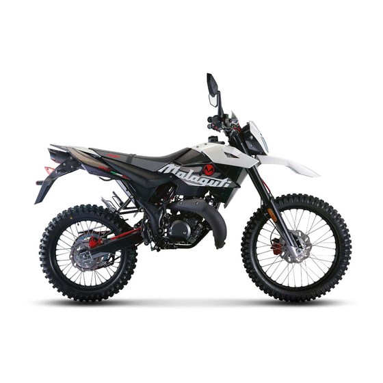
CHASSIS
XTM - XSM
WORKSHOP MANUALS
Table of
Contents
Previous
Page
Next
Page
1
2
3
4
5
Advertisement
Table of Contents
Need help?
Do you have a question about the XTM 50 and is the answer not in the manual?
Ask a question
Questions and answers
Related Manuals for Malaguti XTM 50
Motorcycle Malaguti XSM 50 Workshop Manual
Chassis (42 pages)
Motorcycle Malaguti X3M User Manual
(292 pages)
Motorcycle Malaguti X3Motard Workshop Manual
125cc 4t euro3 (50 pages)
Motorcycle Malaguti XTM POWER UP 2007 Troubleshooting Manual
Electric system (53 pages)
Motorcycle Malaguti XTM 50 2007 Manual
(304 pages)
Motorcycle Malaguti Dune X 125 Service Station Manual
(273 pages)
Motorcycle Malaguti DUNE 125 User Manual
(112 pages)
Motorcycle Malaguti XAM CE Instruction Manual
(48 pages)
Motorcycle Malaguti XAM L1E Instruction Manual
(48 pages)
Motorcycle Malaguti XSM125 2018 User Manual
(112 pages)
Motorcycle Malaguti XTM125 2018 User Manual
(112 pages)
Motorcycle Malaguti CNK 50 DRAKON Workshop Manual
(80 pages)
Motorcycle Malaguti Fast Time F-10 50cc Repair Manual
(151 pages)
Motorcycle Malaguti Grizzly Minicross RCX/12 50CC Service Manual
(34 pages)
Motorcycle Malaguti SPIDER MAX 500 Diagnostic Manual
Of the electrical system and ems injection system (501 pages)
Motorcycle Malaguti Blog 126 Service Manual
Frame and running gear (79 pages)
This manual is also suitable for:
Xsm 50
Table of Contents
Save PDF
Print
Rename the bookmark
Delete bookmark?
Delete from my manuals?
Login
Sign In
OR
Sign in with Facebook
Sign in with Google
Upload manual
Upload from disk
Upload from URL


Need help?
Do you have a question about the XTM 50 and is the answer not in the manual?
Questions and answers