Advertisement
DESCRIPTION
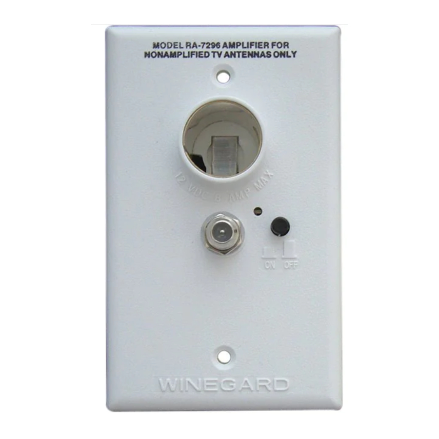
Wall plate/amplifier amplifies VHF/UHF TV signals received by non-amplified Winegard RV antennas with outdoor receptacle for TV set and cable input. Wall plate/amplifier provides a +12 Volt receptacle as well as antenna signals to two TV sets. Cable input from outdoor receptacle connects to wall plate and may be switched so either antenna or cable signals may be watched. See applications. Available in white only.
NOTE: THIS UNIT IS AN AMPLIFIER. USE ONLY WITH NON-AMPLIFIED RV ANTENNAS.

Use this amplifier/ switch with only non-amplified RV antennas.
APPLICATIONS AND ALTERNATE CONNECTIONS

Example 1
Do not connect high current devices such as hair dryers to +12 volt receptacle on wall plate/amplifier. Maximum current ratings of this receptacle is 7.5 amps at +12 VDC.

Example 2
Example 3
INSTRUCTIONS
STEP 1. Select location for wall plate and outdoor receptacle. Run two coax cables (RG59 type) between locations and install connectors on each end. Mark cables so "cable input" and "TV output" may be identified. Antenna downlead and +12 VDC will also be needed at inside wall plate/amplifier location.
STEP 2. Refer to outdoor receptacle instruction sheet on how to install cables and receptacle. Make sure jack on outdoor receptacle marked CABLE INPUT is attached to cable going to jack marked CABLE on indoor wall plate/amplifier.
STEP 3. The wall plate/amplifier assembly may be flush mounted in most standard electrical boxes. To flush mount cut a hole in wall to fit the box. Run 2 #12 wires between wall plate/amplifier and +12 VDC source and route downlead cable to this location. Install cable between set 2 outlet and power supply location at this time.
WHEN CONNECTING CABLE OR WIRES BE SURE SWITCH IS IN OFF POSITION.
STEP 4. Install terminals on wires from +12 VDC source as shown in Figure 1.

Crimp terminals with Craftsman type 4 crimping tool or equivalent. See Figure 1. Push wires onto tabs on terminal board as shown in Figure 2.

If in doubt as to the polarity of the wires, connect them temporarily to tabs on circuit board and press switch on front of outlet. If light comes on polarity is correct. See Figure 3.

STEP 5. Install connectors on downlead and set 2 cable as shown in Figure 5.
Attach downlead cable to jack on wallplate/amplifier marked antenna as shown in Figure 4.

Attach cable going to set 2 outlet to jack on power supply marked SET 2. Attach cable coming from cable input to jack on power supply marked CABLE.
STEP 6. Mount wall plate/amplifier in wall with screws provided and attach TV set cable to jack on front. Connect TV set cable to input jack on TV. Press switch on front of outlet and check that light is on.
OPERATION: To receive cable signals from outdoor receptacle: Press switch to OFF position. Light on wallplate will go (OFF) showing that power is no longer connected to the amplifier and that both TV sets are receiving signals from outdoor receptacle.
To receive signals from antenna: Press switch to ON position. Light on wallplate will come (ON) showing that power is connected to the amplifier and both TV sets are receiving signals from the antenna.
NOTE: Make sure the antenna is in the operating position (up) and pointed at the station desired.
INSTALLING FC-5910 CONNECTORS ON COAX CABLE

Step 1: Strip outer cover back 1/2"* from end of cable. Fray braid back as far as outer cover will allow.
Step 2: Trim braid close to outer cover and remove 1/4"* of inner insulation being careful not to nick center conductor. Make sure no foil or braid can touch center conductor.
Step 3: Slide connector tip between braid and inner insulation (braid and foil, on foil shield cable) and push connector on cable as far as it will go. Crimp built-in ferrule with proper crimping tool. Hex connector requires hex crimping tool. Do Not crush cable out-of-round.
* If installing in very hot weather, increase dimensions 1/8"
WINEGARD COMPANY
3000 KIRKWOOD ST., BURLINGTON, IA 52601-2000

Documents / ResourcesDownload manual
Here you can download full pdf version of manual, it may contain additional safety instructions, warranty information, FCC rules, etc.
Advertisement


Need help?
Do you have a question about the RA-7296 and is the answer not in the manual?
Questions and answers