Table of Contents
Advertisement
Advertisement
Table of Contents

Subscribe to Our Youtube Channel
Related Manuals for Winegard RM-EX02


Summary of Contents for Winegard RM-EX02
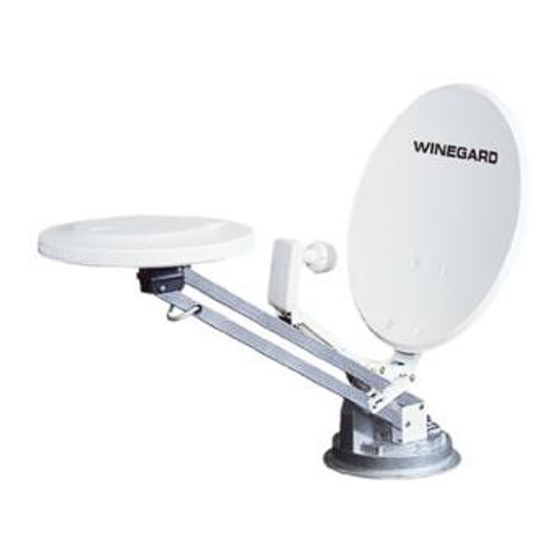
- Page 1 RV DIGITAL SATELLITE SYSTEM with Digital Elevation Sensor Model RM-EX02 Made in U.S.A. Winegard Company • 3000 Kirkwood St. • Burlington, IA 52601-2000 319/754-0600 • FAX 319/754-0787 • www. winegard.com Printed in U.S.A. © Winegard Company 2009 2452168 REV6 12/12...
-
Page 2: Operation
STEP 5. Snap elevation crank in place. STEP 3. Press button on Winegard Digital Display Wall plate. If antenna is in travel position, the display will show LL for Low Limit. HL for High Limit will appear when dish is in up position. -
Page 3: Troubleshooting
(Roof template, see insert.) 3. Be sure cables are not binding, and that they are installed properly. 4. Contact your dealer or Winegard Technical Services. It is highly recommended the antenna be mounted on roof center line. Do not mount antenna closer than 10”... - Page 4 STEP 3. Attach dish to backup. Use bolts and DIGITAL ELEVATION SENSOR ROOF CONNECTIONS (4) Antenna nuts provided, Figure 4. Mounting Bolts The illustrations below show the different methods of connecting wires at roof level; method will depend on mod- STEP 4.
- Page 5 Use ABS (plastic inside surface of crank pipe) glue. handle housing; shaft NOTE: For roofs over 5¼” thick, a longer aluminum hex goes through hex-shaped opening by screw. shaft is needed. Contact Winegard for this part.
- Page 6 Roof Template ALIGN WITH BASEPLATE AREA MARKED “FRONT” POINT TO FRONT OF VEHICLE 1-3/4” DIA. DRILL COMPLETELY THROUGH CEILING 1/8” DRILL BIT 8 HOLES. DO NOT DRILL THROUGH CEILING.
- Page 7 CAUTION! FIGURE 15 After INITIAL INSTALLATION, the antenna SHOULD ROTATE APPROXIMATELY 360° FROM TRAVEL POSITION. The pointer on the DIRECTIONAL HANDLE should point towards the RED SCREW ON THE ROTATION CLAMP when in the TRAVEL Elevating Shaft POSITION. FIGURE 14 ASSEMBLED VIEW Threaded Tube Directional Handle Extension...
-
Page 8: Parts List
STEP 24. Press button on Winegard digital display correct elevation and continue research. wall plate. If antenna is in travel position, the display will show LL for Low Limit. - Page 9 Parts List Parts List 46 cm Reflector (4) Flat Head Bolts LNBF LB-6000 Carriage Bolt (not shown) Back-up Frame Flange Nut 1/4-20 Roller Feed Arm Pivot Bracket P.N. 2744946 Hex Head Bolt 1/4-20 x 2.5” Pin, 1/4 x 3.25” long Screw #10-24 x 3/4 (4) (Not Shown: E-clip for 1/4”...
- Page 10 Notes Notes...
-
Page 11: Specifications
If a defect in material or workmanship is discovered, Customer may take the product to an authorized Winegard dealer for service. Customer must provide proof of purchase to verify the product is under warranty. If the product is brought to an authorized Winegard dealer for service prior to expiration of year one (1) of the warranty period and a defect in material or workmanship is verified by Winegard Technical Services, Winegard Company will cover the Winegard dealer’s labor charges for...
Need help?
Do you have a question about the RM-EX02 and is the answer not in the manual?
Questions and answers