Table of Contents
Advertisement
OWNER'S MANUAL - OPERATION/INSTALLATION INSTRUCTIONS
Model RM-4610, no Digital Magic
Model RM-DM61 with "Digital Magic"
Model RM-DM55 with "Digital Magic"
INSTALL "FRONT" INSCRIBED
ON BASE TOWARD FRONT
OF VEHICLE!
319/754-0600 • FAX 319/754-0787 • www.winegard.com
WINEGARD
RV Digital Satellite System
with RS-1000 Antenna
U.S. PATENT NO. 5,532,710 AND 5,554,998
Made in U.S.A.
Winegard Company • 3000 Kirkwood Street • Burlington, IA 52601
Elevation Sensor
TM
Elevation Sensor
TM
(No Power Supply)
TM
2451070 Rev. 12/21/05
1
®
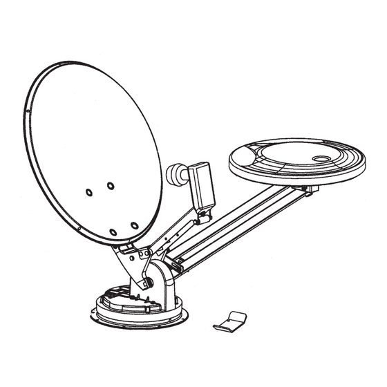
PARTS INCLUDED:
Reflector (dish)
Gasket
RS-1000 antenna
Interior parts
Mount/base assembly
Hardware
Models RM-DM61/DM55
Electronic elevation sensor
Models RM-4610/DM61
Power supply
Advertisement
Table of Contents

Summary of Contents for Winegard RM-DM61/DM55
- Page 1 Model RM-DM61 with “Digital Magic” Model RM-DM55 with “Digital Magic” INSTALL “FRONT” INSCRIBED ON BASE TOWARD FRONT OF VEHICLE! Winegard Company • 3000 Kirkwood Street • Burlington, IA 52601 319/754-0600 • FAX 319/754-0787 • www.winegard.com WINEGARD RV Digital Satellite System with RS-1000 Antenna U.S.
-
Page 2: Finding The Satellite
See your receiver manual for setup information. STEP 3. Press button on Winegard Digital Display wall plate. If the antenna is in travel position, the display will show LL for Low Limit. HL for High Limit will show when dish is in Up position. - Page 3 OPERATIONS DO’S AND DON’T’S DO’S 1. Do check parking location for obstructions before raising antenna. 2. Do carefully raise, lower and rotate the antenna — if difficult, check for cause. 3. Do rotate slowly when searching for the satellite(s) and check fine tuning on TV set for proper adjustment. 4.
-
Page 4: Ordering Repair Parts
5. Do you have +12 VDC at the end of the LNBF cable? Remove cable from LNBF before testing. 6. Contact your dealer or Winegard Technical Services at 800/788-4417. ANTENNA IS HARD TO ROTATE, OR ANTENNA DOES NOT ROTATE 1. -
Page 5: Installation And Assembly
— reinforced roof areas or pre-wire installation done at the factory. THE SYSTEM MUST BE LEVEL FOR PROPER OP- ERATION! Winegard’s RW-5000 roof wedge is available for sloped roofs, Figure 5. If using roof wedge, installer will provide longer mounting screws. Mount base plate and ceiling plate must be parallel with each other, Figure 5. - Page 6 STEP 3. Remove backing from gasket. Attach adhesive side to base plate. IF YOU ARE USING THE ROOF WEDGE (RW-5000), use 3/16” gasket included with the mount UNDER the roof wedge. Install the 1/16” gasket included with RW-5000 BETWEEN the mount and roof wedge.See Figure 7.
- Page 7 STEP 7. Facing the front of the dish, find coax cables attached to side of the feed arm, Figure 9. Measure 24” of coax from this point and mark. DO NOT CUT. Rotate mount on base clockwise, fully, until it stops. Route coax around mount base, Figure 10.
- Page 8 FOR RM-DM61/RM-DM55 ONLY DIGITAL ELEVATION SENSOR ROOF CONNECTIONS The illustrations below show the different methods of connecting wires at roof level. Method will depend on model. Wire colors MUST MATCH (i.e. red to red, green to green, black to black, white to white). This wire harness connects to the digital elevation sensor on the antenna.
- Page 9 Use ABS (plastic pipe) glue. NOTE: For roofs thicker that 5-1/4", a longer aluminum hex shaft will be needed. Contact Winegard Company for this part. CUTTING SHAFT LENGTH, Figure 14A: Flip down handle on the elevating crank handle.
- Page 10 CAUTION: After INITIAL INSTALLATION, the antenna should ROTATE APPROXIMATELY 360° FROM TRAVEL POSITION. The pointer on the DIRECTIONAL HANDLE should point towards the RED SCREW on the ROTATION CLAMP when in TRAVEL POSITION. ASSEMBLED VIEW POINTER MUST POINT TO RED SCREW ON ROTATION CLAMP...
-
Page 11: Exploded Parts View
EXPLODED PARTS VIEW... - Page 12 PARTS LIST INTERIOR HARDWARE KIT RK-CEIL Directional Handle Extension CRANK HANDLE KIT RK-HAND #8-32 x 3/8" Phillips Screw #8-32 Square Nut NOT TO SCALE Rev 6/11/01 #10 x 3/8" Phillips Screw Ceiling Base Directional Dial (4) #10 Phillips Flat Head Screws Azimuth Lock Azimuth Lock Knob Washer...
-
Page 13: Specifications
SPECIFICATIONS Height when raised ... 30” with satellite antenna in vertical position Height in travel position ... 8” Roof space required ... 19.5” x 46.75” Satellite antenna height ... 20.9” Satellite antenna width ... 19.5” Satellite antenna gain— Aperture efficiency ... 73% Cross polarization (on axis) ... -
Page 14: Replacement Parts Kits
REPLACEMENT PARTS KITS HEAD ASSEMBLY RP-RS00 Head w/bracket and nut ... 1 Pins ... 2 E-Clip ... 2 REFLECTOR RP-REFL Dish ... 1 Bolt ... 4 Nut ... 4 BOOM ASSEMBLY RP-BOOM Top boom ... 1 Bottom boom ... 1 Bumper ... -
Page 16: Return Authorization Policy
Winegard Company, 3000 Kirkwood Street, Burlington, Iowa 52601, Telephone 319-754-0600 or visit www.winegard.com). Customer must provide proof of purchase with a dated sales receipt for the Winegard product to verify the product is under warranty. If the date of purchase cannot be verified, the warranty period shall be considered to begin thirty (30) days after the date of manufacture.


Need help?
Do you have a question about the RM-DM61/DM55 and is the answer not in the manual?
Questions and answers