Table of Contents
Advertisement
Quick Links
Advertisement
Table of Contents

Related Manuals for Supermicro MicroBlade MBM-XEM-002


Summary of Contents for Supermicro MicroBlade MBM-XEM-002
- Page 1 ™ 6U/3U MicroBlade Network System Options MBM-XEM-002 10 Gbps MBM-XEM-001 10 Gbps Ethernet Switch Module Ethernet Switch Module MBM-GEM-004 1 Gbps MBM-GEM-001 2.5-Gbps/1 Gbps Ethernet Switch Module Ethernet Switch Module User’s Manual Revison 1.0d...
- Page 2 This product, including software and documentation, is the property of Supermicro and/or its licensors, and is supplied only under a license. Any use or reproduction of this product is not allowed, except as expressly permitted by the terms of said license.
- Page 3 About this Manual This manual is written for professional system integrators, Information Technology professionals, service personnel and technicians. It provides information for the installation and use of Supermicro's network modules. Installation and maintenance should be performed by experienced professionals only. Manual Organization Chapter 1: Introduction The first chapter provides an overview of this manual.
- Page 4 6U/3U MicroBlade Network System Options User’s Manual Notes...
-
Page 5: Table Of Contents
............... 1-1 1-1 Overview ..................... 1-1 1-2 Product Checklist of Typical Components ........1-1 1-3 Features ....................1-1 1-4 Contacting Supermicro ..............1-2 Chapter 2 Standardized Warning Statements ..... 2-1 2-1 About Standardized Warning Statements ........2-1 Warning Definition................... 2-1 Installation Instructions ................ - Page 6 6U/3U MicroBlade Network System Options User’s Manual Locating and Identifying a Switch on a Blade Enclosure ......3-8 Locating and Identifying a Switch Port on a Blade Enclosure....3-8 Chapter 4 Ethernet Modules ............4-1 4-1 MBM-GEM-001 Gigabit Ethernet Switch Module ......
- Page 7 List of Figures Figure 3-1. Installing a Switch Module .............. 3-2 Figure 3-2. Blade Enclosure with Switch Modules Installed......3-3 Figure 3-3. Configuring the Switch Module ............3-4 Figure 3-4. Blade Status Screen ............... 3-5 Figure 3-5. Blade System Screen ..............3-6 Figure 3-6.
- Page 8 6U/3U MicroBlade Network System Options User’s Manual Notes viii...
- Page 9 List of Tables Table 3-1. MBM-GEM-001 Switch Module Address Default Settings ....3-7 Table 3-2. Locating and Identifying a Switch in 628L Enclosure....... 3-8 Table 4-1. MBM-GEM-001 Gigabit Ethernet Switch Module Interface....4-1 Table 4-2. MBM-GEM-001 Gigabit Ethernet Switch Module Features ..... 4-2 Table 4-3.
- Page 10 6U/3U MicroBlade Network System Options User’s Manual Notes...
-
Page 11: Chapter 1 Introduction
• If you have any questions, please contact our support team at: support@supermicor.com Note: A complete list of safety warnings is provided on the Supermicro web site at http://www.supermicro.com/about/policies/safety_information.cfm. Features Chapter 4: " Ethernet Modules" on page 4-1 for information on all Ethernet... -
Page 12: Contacting Supermicro
Address: Super Micro Computer, Inc. 980 Rock Ave. San Jose, CA 95131 U.S.A. Tel: +1 (408) 503-8000 Fax: +1 (408) 503-8008 marketing@supermicro.com (General Information) Email: support@supermicro.com (Technical Support) Website: www.supermicro.com Europe Address: Super Micro Computer B.V. Het Sterrenbeeld 28, 5215 ML ‘s-Hertogenbosch, The Netherlands... -
Page 13: Chapter 2 Standardized Warning Statements
The following statements are industry standard warnings, provided to warn the user of situations which have the potential for bodily injury. Should you have questions or experience difficulty, contact Supermicro's Technical Support department for assistance. Only certified technicians should attempt to install or configure components. - Page 14 6U/3U MicroBlade Network System Options User’s Manual Warnung WICHTIGE SICHERHEITSHINWEISE Dieses Warnsymbol bedeutet Gefahr. Sie befinden sich in einer Situation, die zu Verletzungen führen kann. Machen Sie sich vor der Arbeit mit Geräten mit den Gefahren elektrischer Schaltungen und den üblichen Verfahren zur Vorbeugung vor Unfällen vertraut.
-
Page 15: Installation Instructions
Chapter 2: Standardized Warning Statements 안전을 위한 주의사항 경고! 이 경고 기호는 위험이 있음을 알려 줍니다. 작업자의 신체에 부상을 야기 할 수 있는 상태에 있게 됩니다. 모든 장비에 대한 작업을 수행하기 전에 전기회로와 관련된 위험 요소들을 확인하시고 사전에 사고를 방지할 수 있도록 표준 작업절차를 준수해 주시기 바랍니다. -
Page 16: Circuit Breaker
6U/3U MicroBlade Network System Options User’s Manual Attention Avant de brancher le système sur la source d'alimentation, consulter les directives d'installation. מתח את הוראות התקנה לפני חיבור המערכת למקור יש לקרוא ﻣﺼﺪر ﻟﻠﻄﺎﻗﺔ اﻟﻨﻈﺎم إﻟﻰ ﻗﺒﻞ ﺗﻮﺻﯿﻞ ﺘﺮﻛﯿﺐ اﻗﺮ إرﺷﺎدات اﻟ 시스템을... -
Page 17: Power Disconnection Warning
Chapter 2: Standardized Warning Statements Attention Pour ce qui est de la protection contre les courts-circuits (surtension), ce produit dépend de l'installation électrique du local. Vérifiez que le courant nominal du dispositif de protection n'est pas supérieur à :250 V, 20 A. קצר... - Page 18 6U/3U MicroBlade Network System Options User’s Manual Warnung Das System muss von allen Quellen der Energie und vom Netzanschlusskabel getrennt sein, das von den Spg.Versorgungsteilmodulen entfernt wird, bevor es auf den Chassisinnenraum zurückgreift, um Systemsbestandteile anzubringen oder zu entfernen. ¡Advertencia! El sistema debe ser disconnected de todas las fuentes de energía y del cable eléctrico quitado de los módulos de fuente de alimentación antes de tener acceso el interior del chasis para instalar o para quitar componentes de sistema.
-
Page 19: Equipment Installation
Chapter 2: Standardized Warning Statements Equipment Installation Warning! Only trained and qualified personnel should be allowed to install, replace, or service this equipment. 機器の設置 トレーニングを受け認定された人だけがこの装置の設置、交換、またはサービスを許 可されています。 警告 只有经过培训且具有资格的人员才能进行此设备的安装、更换和维修。 警告 只有經過受訓且具資格人員才可安裝、更換與維修此設備。 Warnung Das Installieren, Ersetzen oder Bedienen dieser Ausrüstung sollte nur geschultem, qualifiziertem Personal gestattet werden. -
Page 20: Restricted Area
6U/3U MicroBlade Network System Options User’s Manual Restricted Area Warning! This unit is intended for installation in restricted access areas. A restricted access area can be accessed only through the use of a special tool, lock and key, or other means of security. (This warning does not apply to workstations). アクセス制限区域... -
Page 21: Battery Handling
Chapter 2: Standardized Warning Statements ﻣﺤﻈﻮرة ﻣﻨﺎطﻖ ﻟﺘﺮﻛﯿﺒﮭﺎ ﻓﻲ ھﺬه اﻟﻮﺣﺪة ﺗﺨﺼﯿﺺ ﺗﻢ ،أداة ﺧﺎﺻﺔ ﻣﻦ ﺧﻼل اﺳﺘﺨﺪام ﻓﻘﻂ ﻣﺤﻈﻮرة ﻣﻨﻄﻘﺔ ﻮل إﻟﻰ ﯾﻤﻜﻦ اﻟﻮﺻ ﻷﻣﺎن وﺳﯿﻠﺔ أﺧﺮى ﻟﻼ أي أو ﻗﻔﻞ وﻣﻔﺘﺎح 경고! 이 장치는 접근이 제한된 구역에 설치하도록 되어있습니다. 특수도구, 잠금 장치 및 키 , 또는... -
Page 22: Redundant Power Supplies
6U/3U MicroBlade Network System Options User’s Manual Attention Danger d'explosion si la pile n'est pas remplacée correctement. Ne la remplacer que par une pile de type semblable ou équivalent, recommandée par le fabricant. Jeter les piles usagées conformément aux instructions du fabricant. ¡Advertencia! Existe peligro de explosión si la batería se reemplaza de manera incorrecta. - Page 23 Chapter 2: Standardized Warning Statements 警告 此部件连接的电源可能不止一个,必须将所有电源断开才能停止给该部件供电。 警告 此裝置連接的電源可能不只一個,必須切斷所有電源才能停止對該裝置的供電。 Warnung Dieses Gerät kann mehr als eine Stromzufuhr haben. Um sicherzustellen, dass der Einheit kein trom zugeführt wird, müssen alle Verbindungen entfernt werden. ¡Advertencia! Puede que esta unidad tenga más de una conexión para fuentes de alimentación. Para cortar por completo el suministro de energía, deben desconectarse todas las conexiones.
-
Page 24: Backplane Voltage
6U/3U MicroBlade Network System Options User’s Manual Backplane Voltage Warning! Hazardous voltage or energy is present on the backplane when the system is operating. Use caution when servicing. バックプレーンの電圧 システムの稼働中は危険な電圧または電力が、バックプレーン上にかかっています。 修理する際には注意ください。 警告 当系统正在进行时,背板上有很危险的电压或能量,进行维修时务必小心。 警告 當系統正在進行時,背板上有危險的電壓或能量,進行維修時務必小心。 Warnung Wenn das System in Betrieb ist, treten auf der Rückwandplatine gefährliche Spannungen oder Energien auf. -
Page 25: Comply With Local And National Electrical Codes
Chapter 2: Standardized Warning Statements Waarschuwing Een gevaarlijke spanning of energie is aanwezig op de backplane wanneer het systeem in gebruik is. Voorzichtigheid is geboden tijdens het onderhoud. Comply with Local and National Electrical Codes Warning! Installation of the equipment must comply with local and national electrical codes. -
Page 26: Product Disposal
6U/3U MicroBlade Network System Options User’s Manual Waarschuwing Bij installatie van de apparatuur moet worden voldaan aan de lokale en nationale elektriciteitsvoorschriften. Product Disposal Warning! Ultimate disposal of this product should be handled according to all national laws and regulations. 製品の廃棄... -
Page 27: Hot Swap Fan Warning
Chapter 2: Standardized Warning Statements Waarschuwing De uiteindelijke verwijdering van dit product dient te geschieden in overeenstemming met alle nationale wetten en reglementen. Hot Swap Fan Warning Warning! Hazardous moving parts. Keep away from moving fan blades. The fans might still be turning when you remove the fan assembly from the chassis. -
Page 28: Gevaarlijk Bewegende Onderdelen. Houd Voldoende Afstand Tot De
Electrical Appliance and Material Safety Law prohibits the use of UL or CSA -certified cables (that have UL/CSA shown on the code) for any other electrical devices than products designated by Supermicro only. 電源コードとACアダプター... - Page 29 Fehlfunktion oder ein Brand entstehen. Elektrische Geräte und Material Safety Law verbietet die Verwendung von UL-oder CSA-zertifizierte Kabel, UL oder CSA auf der Code für alle anderen elektrischen Geräte als Produkte von Supermicro nur bezeichnet gezeigt haben.
- Page 30 Het gebruik van andere kabels en adapters kan leiden tot een storing of een brand. Elektrisch apparaat en veiligheidsinformatiebladen wet verbiedt het gebruik van UL of CSA gecertificeerde kabels die UL of CSA die op de code voor andere elektrische apparaten dan de producten die door Supermicro alleen. 2-18...
-
Page 31: Chapter 3 Setup And Installation
This chapter covers the setup and installation of the MicroBlade Ethernet switch module. SuperMicro has several 10-Gigabit and Gigabit Ethernet switch modules for its system. moduless contain various external Ethernet uplinks. The following pages contain some installation instructions that are common to all switches. -
Page 32: Figure 3-1. Installing A Switch Module
6U/3U MicroBlade Network System Options User’s Manual Figure 3-1. Installing a Switch Module... -
Page 33: Figure 3-2. Blade Enclosure With Switch Modules Installed
Chapter 3: Setup and Installation Figure 3-2. Blade Enclosure with Switch Modules Installed MBM-GEM-001 Switch Module MBM-XEM-001 Switch Module 5. Push the release handle to the closed position. NOTE: After the module has been installed and the handle locked, it will turn on and a POST test will run to verify it is working properly. -
Page 34: Removing A Switch Module
6U/3U MicroBlade Network System Options User’s Manual Removing a Switch Module 1. Pull out the release handle to the open position. 2. Pull the module out of the bay. 3. Replace immediately with another module or with a dummy module cover to maintain airflow integrity. -
Page 35: Web-Based Management Utility/Ipmi
Chapter 3: Setup and Installation Note that any port may be configured as up (active) or down (inactive). All ports are active by default. Web-based Management Utility/IPMI Using the Web-based Management Utility or IPMI is the most user-friendly method of configuring the switch module. -
Page 36: Figure 3-5. Blade System Screen
6U/3U MicroBlade Network System Options User’s Manual The IPMI B screen shown in Figure 3-4 Figure 3-5 is then LADE YSTEM displayed. Figure 3-5. Blade System Screen 3. Clicking on a switch module will display the module in the S panel on the WITCH screen... -
Page 37: Address Defaults
Chapter 3: Setup and Installation Address Defaults The following defaults in Table 3-1 are the default addresses that are initially set. Afterwards, you can change these values within the program. Table 3-1. MBM-GEM-001 Switch Module Address Default Settings Address Default Setting https://192.168.100.102 Default IP Address Default Gateway Address... -
Page 38: Locating And Identifying Switches And Switch Ports On A Blade Enclosure
6U/3U MicroBlade Network System Options User’s Manual Locating and Identifying Switches and Switch Ports on a Blade Enclosure Use this section to help you in locating and identifying the switch ports and switches on a blade enclosure. Locating and Identifying a Switch on a Blade Enclosure When you are looking at the rear of the blade enclosure, you can identify the switch associating with a CMM designation by using the information in Table... -
Page 39: Chapter 4 Ethernet Modules
Chapter 4 Ethernet Modules This chapter covers the Ethernet switch modules available for your MicroBlade enclosure. The Ethernet switch modules can only be installed in the upper and lower left and right module bays. MBM-GEM-001 Gigabit Ethernet Switch Module The MBM-GEM-001 Gigabit Ethernet switch module is a layer 2 Ethernet switch. It includes eight 10-Gb/s uplink (SFP+) ports and fifty-six 1/2.5-Gb/s downlink ports for the MicroBlade's LAN interfaces. -
Page 40: Led Indicators
6U/3U MicroBlade Network System Options User’s Manual Table 4-2. MBM-GEM-001 Gigabit Ethernet Switch Module Features Feature Description Chipset Intel FM5224 Internal: Fifty-six (56) 1/2.5-Gbps downlink ports / External: Eight 10-Gbps Internal/External Ports SFP+ uplink ports or two 40-Gbps QSFP uplink ports Bandwidth 442-Gbps non-blocking Trunking... -
Page 41: Mbm-Gem-004 Gigabit Ethernet Switch Module
Chapter 4: Ethernet Modules MBM-GEM-004 Gigabit Ethernet Switch Module The MBM-GEM-004 Gigabit Ethernet switch module is a layer 2/3 Ethernet switch. This module has two internal Ethernet paths to the CMM(s). The module is used to provide a connection between the Ethernet controller integrated on the mainboard and an external Ethernet device. -
Page 42: Led Indicators
Remote Management Browser-based management Protocols Spanning Tree, Rapid Spanning Tree, Multiple Spanning Tree Power Consumption 55 W Operating System Supermicro OS LED Indicators LED indicators for the MBM-GEM-004 Gigabit Ethernet switch module are listed and described in Table A-2 Appendix Ports... -
Page 43: Mbm-Xem-001 10-Gigabit Ethernet Switch Module
Chapter 4: Ethernet Modules MBM-XEM-001 10-Gigabit Ethernet Switch Module The MBM-XEM-001 10-Gigabit Ethernet switch module is a layer 2 Ethernet switch. This module has two internal Ethernet paths to the CMM(s). This module is used to provide a connection between the Ethernet controller integrated on the mainboard and an external Ethernet device. -
Page 44: Led Indicators
6U/3U MicroBlade Network System Options User’s Manual Table 4-8. MBM-XEM-001 10-Gigabit Ethernet Switch Module Features Feature Description Chipset Intel FM6348 Internal: Fifty-six (56) 10Gbps or 1Gbps downlink ports / External: Four Internal/External Ports 40Gbps QSFP Bandwidth 960-Gbps non-blocking Trunking Link aggregation support Jumbo Frame Support Up to 9kb Remote Management... -
Page 45: Mbm-Xem-002 10-Gigabit Ethernet Switch Module
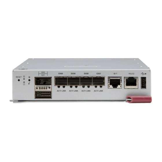
Chapter 4: Ethernet Modules MBM-XEM-002 10-Gigabit Ethernet Switch Module The MBM-XEM-002 10-Gigabit Ethernet switch module is a layer 2 Ethernet switch. This module has two internal Ethernet paths to the CMM(s). This module is used to provide a connection between the Ethernet controller integrated on the mainboard and an external Ethernet device. -
Page 46: Led Indicators
Remote Management Browser-based management Protocols Spanning Tree, Rapid Spanning Tree, Multiple Spanning Tree Power Consumption 85 W Operating System Supermicro OS LED Indicators LED indicators for the MBM-XEM-002 10-Gigabit Ethernet switch module are listed and described in Table A-4 Appendix Ports... -
Page 47: Appendix Aled Descriptions
Appendix A LED Descriptions This appendix covers LED descriptions for the blade enclosure and other module components. MBM-GEM-001 Gigabit Ethernet Module LED Descriptions MBM-GEM-001 Gigabit Ethernet module LEDs are described below in Table A-1. Table A-1. MBM-GEM-001 Gigabit Ethernet Switch LED Indicators State Description Module Initiation OK... -
Page 48: Mbm-Gem-004 Gigabit Ethernet Module Led Descriptions
6U/3U MicroBlade Network System Options User’s Manual MBM-GEM-004 Gigabit Ethernet Module LED Descriptions MBM-GEM-004 Gigabit Ethernet module LEDs are described below in Table A-2. Table A-2. MBM-GEM-004 Gigabit Ethernet Switch LED Indicators State Description Module Initiation OK The MBM-GEM-004 GbE switch module is operational and has Steady On passed the POST (Power-On Self-Test) with no critical faults. -
Page 49: Mbm-Xem-001 10-Gigabit Ethernet Module Led Descriptions
MBM-XEM-001 10-Gigabit Ethernet Module LED Descriptions MBM-XEM-001 10-Gigabit Ethernet module LEDs are described below in Table A-3. Table A-3. MBM-XEM-001 10-Gigabit Ethernet Switch LED Indicators State Description Module Initiation OK The MBM-XEM-001 switch module is operational and has Steady On passed the POST (Power-On Self-Test) with no critical faults. -
Page 50: Mbm-Xem-002 10-Gigabit Ethernet Module Led Descriptions
6U/3U MicroBlade Network System Options User’s Manual MBM-XEM-002 10-Gigabit Ethernet Module LED Descriptions MBM-XEM-002 10-Gigabit Ethernet module LEDs are described below in Table A-4. Table A-4. MBM-XEM-002 10-Gigabit Ethernet Switch LED Indicators State Description Module Initiation OK The MBM-XEM-002 switch module is operational and has Steady On passed the POST (Power-On Self-Test) with no critical faults. - Page 51 Disclaimer The products sold by Supermicro are not intended for and will not be used in life support systems, medical equipment, nuclear facilities or systems, aircraft, aircraft devices, aircraft/emergency communication devices or other critical systems whose failure to perform be reasonably expected to result in significant injury or loss of life or catastrophic property damage.
- Page 52 6U/3U MicroBlade Network System Options User’s Manual...
Need help?
Do you have a question about the MicroBlade MBM-XEM-002 and is the answer not in the manual?
Questions and answers