
Related Manuals for Supermicro MicroBlade MBM-GEM-001


Summary of Contents for Supermicro MicroBlade MBM-GEM-001
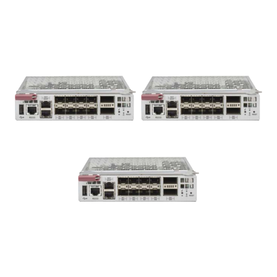
- Page 1 ® MicroBlade Network Modules MBM-GEM-001 2.5-Gbps/1 Gbps MBM-GEM-003i 2.5-Gbps/1 Gbps Ethernet Switch Module Ethernet Switch Module MBM-GEM-003s 2.5-Gbps/1 Gbps Ethernet Switch Module User’s Manual Revison 1.0a...
- Page 2 This product, including software and documentation, is the property of Supermicro and/or its licensors, and is supplied only under a license. Any use or reproduction of this product is not allowed, except as expressly permitted by the terms of said license.
-
Page 3: About This Manual
About this Manual This manual is written for professional system integrators, Information Technology professionals, service personnel and technicians. It provides information for the installation and use of Supermicro's network modules. Installation and maintenance should be performed by experienced professionals only. Manual Organization Chapter 1: Introduction The first chapter provides an overview of this manual. - Page 4 MicroBlade Network Modules User’s Manual Notes...
-
Page 5: Table Of Contents
............... 1-1 1-1 Overview ..................... 1-1 1-2 Product Checklist of Typical Components ........1-1 1-3 Features ....................1-1 1-4 Contacting Supermicro ..............1-2 Chapter 2 Standardized Warning Statements ..... 2-1 2-1 About Standardized Warning Statements ........2-1 Warning Definition................... 2-1 Installation Instructions ................ - Page 6 MicroBlade Network Modules User’s Manual Chapter 4 Ethernet Modules ............4-1 4-1 MBM-GEM-001 Gigabit Ethernet Switch Module ......4-1 LED Indicators ..................4-2 Ports......................4-2 4-2 MBM-GEM-003i Gigabit Ethernet Switch Module ......4-3 LED Indicators ..................4-4 Ports......................4-4 4-3 MBM-GEM-003s Gigabit Ethernet Switch Module .......
- Page 7 List of Figures Figure 3-1. Installing a Switch Module .............. 3-1 Figure 3-2. Blade Enclosure with Switch Modules Installed......3-2 Figure 3-3. Configuring the Switch Module ............3-3 Figure 3-4. Blade Status Screen ............... 3-4 Figure 3-5. Blade System Screen ..............3-5 Figure 3-6.
- Page 8 MicroBlade Network Modules User’s Manual Notes viii...
- Page 9 List of Tables Table 3-1. MBM-GEM-001 Switch Module Address Default Settings ....3-6 Table 3-2. Locating and Identifying a Switch ............ 3-7 Table 3-3. MBE-628L Enclosures with MicroBlade Switches ......3-8 Table 4-1. MBM-GEM-001 Gigabit Ethernet Switch Module Interface....4-1 Table 4-2.
- Page 10 MicroBlade Network Modules User’s Manual Notes...
-
Page 11: Chapter 1 Introduction
• If you have any questions, please contact our support team at: support@supermicor.com Note: A complete list of safety warnings is provided on the Supermicro web site at http://www.supermicro.com/about/policies/safety_information.cfm. Features Chapter 4: "Ethernet Modules" on page 4-1 for information on all Ethernet... -
Page 12: Contacting Supermicro
Address: Super Micro Computer, Inc. 980 Rock Ave. San Jose, CA 95131 U.S.A. Tel: +1 (408) 503-8000 Fax: +1 (408) 503-8008 marketing@supermicro.com (General Information) Email: support@supermicro.com (Technical Support) Website: www.supermicro.com Europe Address: Super Micro Computer B.V. Het Sterrenbeeld 28, 5215 ML ‘s-Hertogenbosch, The Netherlands... -
Page 13: Chapter 2 Standardized Warning Statements
The following statements are industry standard warnings, provided to warn the user of situations which have the potential for bodily injury. Should you have questions or experience difficulty, contact Supermicro's Technical Support department for assistance. Only certified technicians should attempt to install or configure components. - Page 14 MicroBlade Network Modules User’s Manual Warnung WICHTIGE SICHERHEITSHINWEISE Dieses Warnsymbol bedeutet Gefahr. Sie befinden sich in einer Situation, die zu Verletzungen führen kann. Machen Sie sich vor der Arbeit mit Geräten mit den Gefahren elektrischer Schaltungen und den üblichen Verfahren zur Vorbeugung vor Unfällen vertraut.
-
Page 15: Installation Instructions
Chapter 2: Standardized Warning Statements BELANGRIJKE VEILIGHEIDSINSTRUCTIES Dit waarschuwings symbool betekent gevaar. U verkeert in een situatie die lichamelijk letsel kan veroorzaken. Voordat u aan enige apparatuur gaat werken, dient u zich bewust te zijn van de bij een elektrische installatie betrokken risico's en dient u op de hoogte te zijn van de standaard procedures om ongelukken te voorkomen. -
Page 16: Circuit Breaker
MicroBlade Network Modules User’s Manual מתח את הוראות התקנה לפני חיבור המערכת למקור יש לקרוא ﻣﺼﺪر ﻟﻠﻄﺎﻗﺔ اﻟﻨﻈﺎم إﻟﻰ ﻗﺒﻞ ﺗﻮﺻﯿﻞ ﺘﺮﻛﯿﺐ اﻗﺮ إرﺷﺎدات اﻟ Waarschuwing Raadpleeg de installatie-instructies voordat u het systeem op de voedingsbron aansluit. Circuit Breaker Warning! This product relies on the building's installation for short-circuit (overcurrent) protection. -
Page 17: Power Disconnection Warning
Chapter 2: Standardized Warning Statements ﻓﻲ اﻟﺘﻲ ﺗﻢ ﺗﺜﺒﯿﺘﮭﺎ ﻣﻦ اﻟﺪواﺋﺮاﻟﻘﺼﯿﺮة اﻟﺤﻤﺎﯾﺔ ﻣﻌﺪات ﯾﻌﺘﻤﺪ ﻋﻠﻰ ھﺬا اﻟﻤﻨﺘﺞ اﻟﻤﺒﻨﻰ أﻛﺜﺮ ﻣﻦ ﻟﯿﺲ ﻮﻗﺎﺋﻲ اﻟ اﻟﺠﮭﺎز ﺗﻘﯿﯿﻢ أن ﺗﺄﻛﺪ ﻣﻦ 20A, 250V Waarschuwing Dit product is afhankelijk van de kortsluitbeveiliging (overspanning) van uw electrische installatie. -
Page 18: Equipment Installation
MicroBlade Network Modules User’s Manual ¡Advertencia! El sistema debe ser disconnected de todas las fuentes de energía y del cable eléctrico quitado de los módulos de fuente de alimentación antes de tener acceso el interior del chasis para instalar o para quitar componentes de sistema. Attention Le système doit être débranché... -
Page 19: Restricted Area
Chapter 2: Standardized Warning Statements Warnung Das Installieren, Ersetzen oder Bedienen dieser Ausrüstung sollte nur geschultem, qualifiziertem Personal gestattet werden. ¡Advertencia! Solamente el personal calificado debe instalar, reemplazar o utilizar este equipo. Attention Il est vivement recommandé de confier l'installation, le remplacement et la maintenance de ces équipements à... - Page 20 MicroBlade Network Modules User’s Manual Warnung Diese Einheit ist zur Installation in Bereichen mit beschränktem Zutritt vorgesehen. Der Zutritt zu derartigen Bereichen ist nur mit einem Spezialwerkzeug, Schloss und Schlüssel oder einer sonstigen Sicherheitsvorkehrung möglich. ¡Advertencia! Esta unidad ha sido diseñada para instalación en áreas de acceso restringido. Sólo puede obtenerse acceso a una de estas áreas mediante la utilización de una herramienta especial, cerradura con llave u otro medio de seguridad.
-
Page 21: Battery Handling
Chapter 2: Standardized Warning Statements Battery Handling Warning! There is the danger of explosion if the battery is replaced incorrectly. Replace the battery only with the same or equivalent type recommended by the manufacturer. Dispose of used batteries according to the manufacturer's instructions. 警告... -
Page 22: Redundant Power Supplies
MicroBlade Network Modules User’s Manual Waarschuwing Er is ontploffingsgevaar indien de batterij verkeerd vervangen wordt. Vervang de batterij slechts met hetzelfde of een equivalent type die door de fabrikant aanbevolen wordt. Gebruikte batterijen dienen overeenkomstig fabrieksvoorschriften afgevoerd te worden. Redundant Power Supplies Warning! This unit might have more than one power supply connection. -
Page 23: Backplane Voltage
Chapter 2: Standardized Warning Statements اﻣﺪاد اﻟﻄﺎﻗﺔ ﺑﻮﺣﺪات ﻋﺪة اﺗﺼﺎﻻت ﺠﮭﺎز اﻟ ﯾﻜﻮن ﻟﮭﺬا ﻗﺪ اﻟﻜﮭﺮﺑﺎء ﻋﻦ ﻮﺣﺪة اﻟ ﻟﻌﺰل ﻛﺎﻓﺔ اﻻﺗﺼﺎﻻت ﯾﺠﺐ إزاﻟﺔ Waarschuwing Deze eenheid kan meer dan één stroomtoevoeraansluiting bevatten. Alle aansluitingen dienen verwijderd te worden om het apparaat stroomloos te maken Backplane Voltage Warning! Hazardous voltage or energy is present on the backplane when the system is... -
Page 24: Comply With Local And National Electrical Codes
MicroBlade Network Modules User’s Manual اﻟﻠﻮﺣﺔ أواﻟﻄﺎﻗﺔ اﻟﻤﻮﺟﻮدة ﻋﻠﻰ اﻟﺘﯿﺎر اﻟﻜﮭﺮﺑﺎﺋﻲ ﻣﻦ ﺧﻄﺮ ھﻨﺎك ھﺬا اﻟﺠﮭﺎز ﺧﺪﻣﺔ ﻛﻦ ﺣﺬرا ﻋﻨﺪ ﯾﻌﻤﻞ اﻟﻨﻈﺎم ﻋﻨﺪﻣﺎ ﯾﻜﻮن Waarschuwing Een gevaarlijke spanning of energie is aanwezig op de backplane wanneer het systeem in gebruik is. Voorzichtigheid is geboden tijdens het onderhoud. Comply with Local and National Electrical Codes Warning! Installation of the equipment must comply with local and national electrical... -
Page 25: Product Disposal
Chapter 2: Standardized Warning Statements Waarschuwing Bij installatie van de apparatuur moet worden voldaan aan de lokale en nationale elektriciteitsvoorschriften. Product Disposal Warning! Ultimate disposal of this product should be handled according to all national laws and regulations. 警告 本产品的废弃处理应根据所有国家的法律和规章进行。 警告... -
Page 26: Hot Swap Fan Warning
MicroBlade Network Modules User’s Manual Waarschuwing De uiteindelijke verwijdering van dit product dient te geschieden in overeenstemming met alle nationale wetten en reglementen. Hot Swap Fan Warning Warning! The fans might still be turning when you remove the fan assembly from the chassis. -
Page 27: Power Cable And Ac Adapter
Electrical Appliance and Material Safety Law prohibits the use of UL or CSA -certified cables (that have UL/CSA shown on the code) for any other electrical devices than products designated by Supermicro only. 警告... - Page 28 Fehlfunktion oder ein Brand entstehen. Elektrische Geräte und Material Safety Law verbietet die Verwendung von UL-oder CSA-zertifizierte Kabel, UL oder CSA auf der Code für alle anderen elektrischen Geräte als Produkte von Supermicro nur bezeichnet gezeigt haben.
- Page 29 Het gebruik van andere kabels en adapters kan leiden tot een storing of een brand. Elektrisch apparaat en veiligheidsinformatiebladen wet verbiedt het gebruik van UL of CSA gecertificeerde kabels die UL of CSA die op de code voor andere elektrische apparaten dan de producten die door Supermicro alleen. 2-17...
- Page 30 MicroBlade Network Modules User’s Manual Notes 2-18...
-
Page 31: Chapter 3 Setup And Installation
This chapter covers the setup and installation of the MicroBlade Ethernet switch module. SuperMicro has three Gigabit Ethernet switch module for its system. This is the MBM-GEM-001, MBM-GEM-003i and MBM-GEM-003S Gigabit Ethernet switch modules with eight external 10Gbps or two 40Gbps Ethernet uplinks. The following pages contain some installation instructions that are common to both switches. -
Page 32: Removing A Switch Module
MicroBlade Network Modules User’s Manual Figure 3-2. Blade Enclosure with Switch Modules Installed MBM-GEM-003i Switch Module MBM-GEM-001 Switch Module 5. Push the release handle to the closed position. NOTE: After the module has been installed and the handle locked, it will turn on and a POST test will run to verify it is working properly. -
Page 33: Configuring The Switch Module
Chapter 3: Setup and Installation Configuring the Switch Module Figure 3-3. Configuring the Switch Module A Gigabit Ethernet switch module can be configured using two methods (as shown in Figure 3-3). You may configure it: • Through the web-based management utility or IPMI (via the CMM module) •... -
Page 34: Web-Based Management Utility/Ipmi
MicroBlade Network Modules User’s Manual Web-based Management Utility/IPMI Using the Web-based Management Utility or IPMI is the most user-friendly method of configuring the switch module. You can access the configuration menu either through the management utility or by a network connection. Network Connection Use the procedure below to connect and login to the IPMI system. -
Page 35: Figure 3-5. Blade System Screen
Chapter 3: Setup and Installation Figure 3-5. Blade System Screen 3. Clicking on a gigabit switch module will display the gigabit switch in the Gigabit Switch panel on the screen (Figure 3-6). You may make changes in the configuration of the switch module in this panel to your needs. Figure 3-6. -
Page 36: Address Defaults
MicroBlade Network Modules User’s Manual Address Defaults The following defaults in Table 3-1 are the default addresses that are initially set. Afterwards, you can change these values within the program. Table 3-1. MBM-GEM-001 Switch Module Address Default Settings Address Default Setting https://192.168.100.100 Default IP Address Default Gateway Address... -
Page 37: Locating And Identifying Switches And Switch Ports On A Blade Enclosure
Chapter 3: Setup and Installation Locating and Identifying Switches and Switch Ports on a Blade Enclosure Use this section to help you in locating and identifying the switch ports and switches on a blade enclosure. Locating and Identifying a Switch on a Blade Enclosure When you are looking at the rear of the blade enclosure, you can identify the switch associating with a CMM designation by using the information in Table... -
Page 38: Table 3-3. Mbe-628L Enclosures With Microblade Switches
MicroBlade Network Modules User’s Manual Table 3-3. MBE-628L Enclosures with MicroBlade Switches Blade Upper Switch Lower Switch Switch Port # Blade1 NIC2 NIC1 Gi 0/1 Blade 2 NIC2 NIC1 Gi 0/2 Blade 3 NIC2 NIC1 Gi 0/3 Blade 4 NIC2 NIC1 Gi 0/4 Blade 5... -
Page 39: Chapter 4 Ethernet Modules
Chapter 4 Ethernet Modules This chapter covers the Ethernet switch modules available for your MicroBlade enclosure. The Ethernet switch modules can only be installed in the upper and lower left and right module bays. MBM-GEM-001 Gigabit Ethernet Switch Module The MBM-GEM-001 Gigabit Ethernet switch module is a layer 2 Ethernet switch. It includes eight 10-Gb/s uplink (SFP+) ports and fifty-six 1/2.5-Gb/s downlink ports for the MicroBlade's LAN interfaces. -
Page 40: Led Indicators
MicroBlade Network Modules User’s Manual Table 4-2. MBM-GEM-001 Gigabit Ethernet Switch Module Features Feature Description Chipset Intel FM5224 Internal: Fifty-six (56) 2.5-Gbps downlink ports / External: Eight 10-Gbps Internal/External Ports RJ45 uplink ports Bandwidth 442-Gbps non-blocking Trunking Link aggregation support Jumbo Frame Support Up to 9kb Remote Management... -
Page 41: Mbm-Gem-003I Gigabit Ethernet Switch Module
Chapter 4: Ethernet Modules MBM-GEM-003i Gigabit Ethernet Switch Module The MBM-GEM-003i Gigabit Ethernet switch module is a layer 2/3 Ethernet switch. The Gigabit Ethernet switch module has two internal Ethernet paths to the CMM(s). The switch is used to provide a connection between the Ethernet controller integrated on the mainboard and an external Ethernet device. -
Page 42: Led Indicators
MicroBlade Network Modules User’s Manual Table 4-5. MBM-GEM-003i Gigabit Ethernet Switch Module Features Feature Description Chipset Intel FM5224 Internal: Fifty-six (56) 2.5-Gbps downlink ports / External: Eight 10-Gbps Internal/External Ports RJ45 uplink ports Bandwidth 442-Gbps non-blocking Trunking Link aggregation support Jumbo Frame Support Up to 9kb Remote Management... -
Page 43: Mbm-Gem-003S Gigabit Ethernet Switch Module
Chapter 4: Ethernet Modules MBM-GEM-003s Gigabit Ethernet Switch Module The MBM-GEM-003s Gigabit Ethernet switch module is a layer 2 Ethernet switch. The Gigabit Ethernet switch module has two internal Ethernet paths to the CMM(s). The switch is used to provide a connection between the Ethernet controller integrated on the mainboard and an external Ethernet device. -
Page 44: Led Indicators
MicroBlade Network Modules User’s Manual Table 4-8. MBM-GEM-003s Gigabit Ethernet Switch Module Features Feature Description Chipset Intel FM5224 Internal: Fifty-six (56) 2.5-Gbps downlink ports / External: Eight 10-Gbps Internal/External Ports RJ45 uplink ports Bandwidth 442-Gbps non-blocking Trunking Link aggregation support Jumbo Frame Support Up to 9kb Remote Management... -
Page 45: Appendix Aled Descriptions
Appendix A LED Descriptions This appendix covers LED descriptions for the blade enclosure and other module components. MBM-GEM-001 Gigabit Ethernet Module LED Descriptions MBM-GEM-001 Gigabit Ethernet module LEDs are described below in Table A-1. Table A-1. MBM-GEM-001 Gigabit Ethernet Switch LED Indicators State Description Module Initiation OK... -
Page 46: Mbm-Gem-003I Gigabit Ethernet Module Led Descriptions
MicroBlade Network Modules User’s Manual MBM-GEM-003i Gigabit Ethernet Module LED Descriptions MBM-GEM-003i Gigabit Ethernet module LEDs are described below in Table A-1. Table A-2. MBM-GEM-003i Gigabit Ethernet Switch LED Indicators State Description The MBM-GEM-003i GbE switch module is operational and Module Initiation OK Steady On has passed the POST (Power-On Self-Test) with no critical... -
Page 47: Mbm-Gem-003S Gigabit Ethernet Module Led Descriptions
MBM-GEM-003s Gigabit Ethernet Module LED Descriptions MBM-GEM-003s Gigabit Ethernet module LEDs are described below in Table A-1. Table A-3. MBM-GEM-003s Gigabit Ethernet Switch LED Indicators State Description The MBM-GEM-003s GbE switch module is operational and Module Initiation OK Steady On has passed the POST (Power-On Self-Test) with no critical faults. - Page 48 MicroBlade Network Modules User’s Manual Notes...
- Page 49 Disclaimer The products sold by Supermicro are not intended for and will not be used in life support systems, medical equipment, nuclear facilities or systems, aircraft, aircraft devices, aircraft/emergency communication devices or other critical systems whose failure to perform be reasonably expected to result in significant injury or loss of life or catastrophic property damage.
- Page 50 MicroBlade Network Modules User’s Manual...
Need help?
Do you have a question about the MicroBlade MBM-GEM-001 and is the answer not in the manual?
Questions and answers