Table of Contents
Advertisement
Available languages
Available languages
Quick Links
Advertisement
Chapters
Table of Contents

Related Manuals for ProLights ECLFR2KPTW


Summary of Contents for ProLights ECLFR2KPTW
- Page 1 ECLFR2KPTW POLE OPERATED FRESNEL PROJECTOR USER MANUAL MANUALE UTENTE EN - IT...
- Page 2 All rights reserved by Music & Lights S.r.l. No part of this instruction manual may be reproduced in any form or by any means for any commercial use. In order to improve the quality of products, Music&Lights S.r.l. reserves the right to modify the characteristics stated in this instruction manual at any time and without prior notice.
-
Page 3: Table Of Contents
4 Maintenance 4. 1 Maintenance and cleaning the unit 4. 1 Maintenance and cleaning the unit 4. 2 Trouble shooting 4. 2 Trouble shooting Packing content • ECLFR2KPTW • ECLFR2KTPG • ECLFR2KBD • ECLFRSPG • Power cable • User manual... - Page 4 ECLFR2KPTW WARNING! Before carrying out any operations with the unit, carefully read this instruction manual and keep it with cure for future reference. It contains important information about the installation, usage and maintenance of the unit. SYMBOLS ELECTRIC SHOCK RISK...
-
Page 5: General Instructions
ECLFR2KPTW WARNING! Before carrying out any operations with the unit, carefully read this instruction manual and keep it with cure for future reference. It contains important information about the installation, usage and maintenance of the unit. SAFETY General instruction • This unit is not for home use, only professional applications. -
Page 6: Photobiological Safety
ECLFR2KPTW WARNING! Before carrying out any operations with the unit, carefully read this instruction manual and keep it with cure for future reference. It contains important information about the installation, usage and maintenance of the unit. Photobiological safety • This device is a product identified in risk group 2 according to EN 62471. -
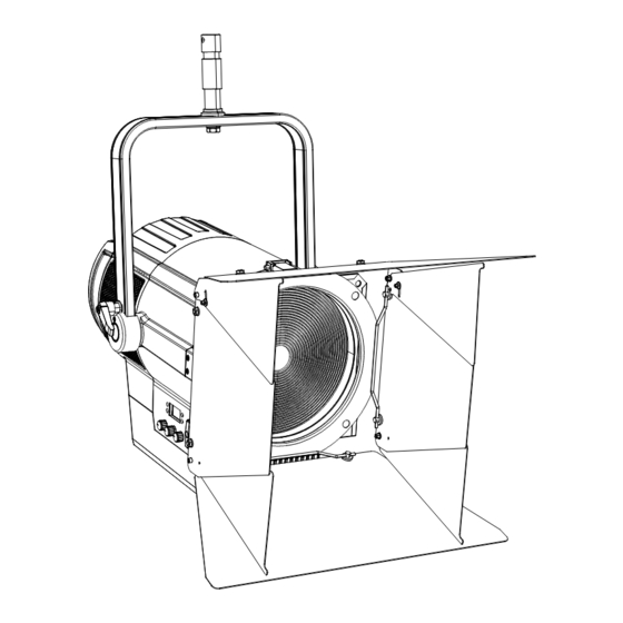
Page 7: Technical Drawing
ECLFR2KPTW - 1 - TECHNICAL DRAWING Technical drawing Fig.1... -
Page 8: Operating Elements And Connections
ECLFR2KPTW 1.1 OPERATING ELEMENTS AND CONNECTIONS 11 12 13 14 Rear view Side view Fig.2 1. VENTILATION GRID for air flow outlet not to be 10. MAIN FUSE HOLDER: replace a burnt-out fuse by obstructed. one of the same type only 2. -
Page 9: Installation
20 cm. The adjust the projector and use the knobs. NOTE - For the installation of the ECLFR2KPTW make sure that the ridge of the adaptor is in with the groove of the track. -
Page 10: Functions And Settings
- 3 - FUNCTIONS AND SETTINGS 3.1 OPERATION To turn ECLFR2KPTW connect the supplied main cable to a socket (100-240 VAC-50/60 Hz). Then the unit is ready for operation and can be operated via a DMX controller. To switch off, disconnect the mains plug from the socket. -
Page 11: Menu Structure
ECLFR2KPTW 3.3 MENU STRUCTURE MENU CONNECT ð DMX Address ð Value (001-512) Default: 1 DMX Mode ð ð Amber Shift on ð ð Color CTO 2800 - 10000K Temperature Hue (025~025) ð Color Picker ð 3200K ð Customization ð Red (000~255) - Page 12 ECLFR2KPTW ADVANCED ð ð Full On Mode Default: Studio Studio Dimmer Mode ð Default: Off Dimmer 1 Dimmer 2 Dimmer 3 White Balance ð Adjust ð Red (125~255) Default: Off Orange (125~255) Green (125~255) Royal Blue (125~255) Blue (125~255) Lime (125~255) Led Frequency ð...
- Page 13 ECLFR2KPTW ð ð Fixed Color R.O.G R.O.G.B Dimmer (000~255) Default: R.O.RB R.O.G.L R.O.G.RB.B.L R.O.B R.O.RB.B Dimmer=255 R.O.L R.O.RB.L R.G.RB R.O.B.L R.G.B R.G.RB.B R.G.L R.G.RB.L R.RB.B R.G.B.L R.RB R.RB.L R.RB.B.L R.B.L O.G.RB.B O.G.RB O.G.RB.L O.G.B O.G.B.L O.RB O.G.L O.RB.B.L O.RB.B G.RB.B.L O.RB.L...
-
Page 14: Dmx Addressing
• Press the MENU button to go back or to meet the waiting time to exit the setup menu. The tables on page 15, 16, 17, 18, 19, 20, 21 indicate the operating mode and DMX value. The ECLFR2KPTW is equipped with 5-pole XLR connections. -
Page 15: Screen
ECLFR2KPTW Numero Indirizzo di Indirizzo DMX Prossimo indirizzo di start Prossimo indirizzo di start Prossimo indirizzo di start canali DMX start (esempio) occupati possibile per unità n°1 possibile per unità n°2 possibile per unità n°3 33-34 33 - 37 33 - 39... -
Page 16: Information
ECLFR2KPTW maxinum value of the colors) or Studio mode with a automatic white balance. - Dimmer Mode - Adjusting the dimmer. Enter in Dimmer Mode to select specific dimming curve. Particularly when set: • Off: The increase in light intensity is linear. -
Page 17: Fixed Color
ECLFR2KPTW 3.12 FIXED COLORS This fixture has the ability to accept custom static color settings. Access these chases via the control panel on the back of the fixture. • Press the MENU button so many times until the display shows Stand Alone, then press the ENTER button. -
Page 18: Dmx Control
ECLFR2KPTW 3.14 CHANNELS DMX 1 CHANNEL 5 CHANNELS 1 MODE MODE FUNCTION FUNCTION Value Value 5 Ch1 1 Ch DIMMER DIMMER 0~100% 000 - 255 0~100% 000 - 255 2800K - 3000K 000 - 007 3000K - 3200K 007 - 014... - Page 19 ECLFR2KPTW 5 CHANNELS 2 7 CHANNELS 1 MODE MODE FUNCTION FUNCTION Value 5 Ch2 Value 7 Ch1 DIMMER 0~100% 000 - 255 0~100% 000 - 255 DIMMER FINE ORANGE 0~100% 000 - 255 0~100% 000 - 255 GREEN 000 - 007...
- Page 20 ECLFR2KPTW 8 CHANNELS 8 CHANNELS MODE MODE FUNCTION FUNCTION Value Value 8 Ch 8 Ch COLOR PICKER 212 - 215 No Funciton 000 - 000 216 - 219 3200K 001 - 003 220 - 223 004 - 007 224 - 227...
- Page 21 ECLFR2KPTW 9 CHANNELS 12 CHANNELS MODE MODE FUNCTION FUNCTION Value Value 9 Ch 12 Ch DIMMER DIMMER 0~100% 000 - 255 0~100% 000 - 255 STROBE No Function 000 - 010 0~100% 000 - 255 Strobe slow to fast 011 - 255...
- Page 22 ECLFR2KPTW 12 CHANNELS 16 CHANNELS MODE MODE FUNCTION FUNCTION Value Value 12 Ch 16 Ch DIMMER 000 - 000 0~100% 000 - 255 -25°~25° 001 - 255 DIMMER FINE COLOR MACRO 0~100% 000 - 255 No Function 000 - 002...
- Page 23 ECLFR2KPTW 19 CHANNELS 19 CHANNELS MODE MODE FUNCTION FUNCTION Value Value 19 Ch 19 Ch DIMMER 6800K - 7000K 140 - 147 7000K - 7200K 147 - 154 0~100% 000 - 255 7200K - 7400K 154 - 161 DIMMER FINE...
- Page 24 ECLFR2KPTW 21 CHANNELS 21 CHANNELS MODE MODE FUNCTION FUNCTION Value Value 21 Ch 21 Ch DIMMER RED FINE 0~100% 000 - 255 0~100% 000 - 255 DIMMER FINE ORANGE 0~100% 000 - 255 0~100% 000 - 255 ORANGE FINE STROBE...
-
Page 25: Connection Of The Dmx Line
ECLFR2KPTW 3.15 CONNECTION OF THE DMX LINE DMX connection employs standard XLR connectors. Use shielded pair-twisted cables with 120Ω imped- ance and low capacity. The following diagram shows the connection mode: DMX - INPUT DMX - OUTPUT XLR plug XLR socket... -
Page 26: Maintenance
ECLFR2KPTW - 4 - MAINTENANCE 4.1 MAINTENANCE AND CLEANING THE UNIT • Make sure the area below the installation place is free from unwanted persons during setup. • Switch off the unit, unplug the main cable and wait until the unit has cooled down. - Page 28 Music & Lights S.r.l. si riserva ogni diritto di elaborazione in qualsiasi forma delle presenti istruzioni per l’uso. La riproduzione - anche parziale - per propri scopi commerciali è vietata. Al fine di migliorare la qualità dei prodotti, la Music&Lights S.r.l. si riserva la facoltà di modificare, in qualunque momento e senza preavviso, le specifiche menzionate nel presente manuale di istruzioni.
-
Page 29: Eclfr2Ktpg
4. 1 Manutenzione e pulizia del sistema ottico 4. 1 Manutenzione e pulizia del sistema ottico 4. 2 Risoluzione dei problemi 4. 2 Risoluzione dei problemi Contenuto dell'imballo: • ECLFR2KPTW • ECLFR2KTPG • ECLFR2KBD • ECLFRSPG • Cavo di alimentazione... -
Page 30: Simboli
ECLFR2KPTW ATTENZIONE! Prima di effettuare qualsiasi operazione con l’unità, leggere con attenzione questo manuale e conservarlo accuratamente per riferimenti futuri. Contiene informazioni importanti riguardo l’installazione, l’uso e la manutenzione dell’unità. SIMBOLI RISCHIO DI SCOSSE ELETTRICHE LEGGERE IL MANUALE UTENTE RISCHIO GENERALE / ATTENZIONE... -
Page 31: Avvertenze Generali
ECLFR2KPTW ATTENZIONE! Prima di effettuare qualsiasi operazione con l’unità, leggere con attenzione questo manuale e conservarlo accuratamente per riferimenti futuri. Contiene informazioni importanti riguardo l’installazione, l’uso e la manutenzione dell’unità. SICUREZZA Avvertenze generali • L’unità non per uso domestico, solo per uso professionale. -
Page 32: Sicurezza Fotobiologica
ECLFR2KPTW ATTENZIONE! Prima di effettuare qualsiasi operazione con l’unità, leggere con attenzione questo manuale e conservarlo accuratamente per riferimenti futuri. Contiene informazioni importanti riguardo l’installazione, l’uso e la manutenzione dell’unità. Sicurezza fotobiologica • Questo dispositivo è un prodotto identificato nel gruppo di rischio 2 secondo EN 62471. -
Page 33: Disegno Tecnico
ECLFR2KPTW - 1 - DISEGNI TECNICO Disegno tecnico Fig.1... -
Page 34: Elementi Di Comando E Di Collegamento
ECLFR2KPTW 1.1 ELEMENTI DI COMANDO E COLLEGAMENTI 11 12 13 14 Pannello posteriore Fig.2 Pannello laterale 1. GRIGLIA DI VENTILAZIONE per uscita flusso 11. POWER IN (PowerCON TRUE IN): per il d'aria da non ostruire. collegamento ad una presa di rete (100-240V~/50- 2. -
Page 35: Installazione
20 cm. Quindi orientare il proiettore. NOTA - Per l’installazione del proiettore ECLFR2KPTW inserire il gancio o un morsetto idoneo per fissarlo ad un sistema sospeso. È assolutamente necessario proteggere l’unità per mezzo di una fune di sicurezza. -
Page 36: Funzioni E Impostazioni
Per maggiore comodità è consigliabile collegare l’unità con una presa comandata da un interruttore. 3.2 IMPOSTAZIONE BASE Il ECLFR2KPTW dispone di un display e 4 pulsanti per accesso alle funzioni del pannello di controllo (fig.4). Menu Enter... -
Page 37: Struttura Menù
ECLFR2KPTW 3.3 STRUTTURA MENU MENU CONNECT ð DMX Address ð Value (001-512) Default: 1 DMX Mode ð ð Amber Shift on ð ð Color CTO 2800 - 10000K Temperature Hue (025~025) ð Color Picker ð 3200K ð Customization ð Red (000~255) - Page 38 ECLFR2KPTW ADVANCED ð ð Full On Mode Default: Studio Studio Dimmer Mode ð Default: Off Dimmer 1 Dimmer 2 Dimmer 3 White Balance ð Adjust ð Red (125~255) Default: Off Orange (125~255) Green (125~255) Royal Blue (125~255) Blue (125~255) Lime (125~255) Led Frequency ð...
- Page 39 ECLFR2KPTW ð ð Fixed Color R.O.G R.O.G.B Dimmer (000~255) Default: R.O.RB R.O.G.L R.O.G.RB.B.L R.O.B R.O.RB.B Dimmer=255 R.O.L R.O.RB.L R.G.RB R.O.B.L R.G.B R.G.RB.B R.G.L R.G.RB.L R.RB.B R.G.B.L R.RB R.RB.L R.RB.B.L R.B.L O.G.RB.B O.G.RB O.G.RB.L O.G.B O.G.B.L O.RB O.G.L O.RB.B.L O.RB.B G.RB.B.L O.RB.L...
-
Page 40: Modalità Dmx
DMX per il primo canale DMX. Se, per esempio, sull’unità di comando è previsto l’indirizzo 33 per coman- dare la funzione del primo canale DMX, si deve impostare sul ECLFR2KPTW l’indirizzo di start 33. Le altre funzioni del pannello saranno assegnate automaticamente agli indirizzi successivi. Segue un esempio con indirizzo 33 di start: 3.5 CONFIGURAZIONE CANALI DMX... -
Page 41: Screen
ECLFR2KPTW Numero Indirizzo di Indirizzo DMX Prossimo indirizzo di start Prossimo indirizzo di start Prossimo indirizzo di start canali DMX start (esempio) occupati possibile per unità n°1 possibile per unità n°2 possibile per unità n°3 33-34 33 - 37 33 - 39... -
Page 42: Informazioni Sul Dispositivo
• Premere il tasto MENU per uscire dal menu e per salvare le modifiche apportate. • Servirsi dei connettori DMX del ECLFR2KPTW e di un cavo XLR per formare una catena di unità. In certe condizioni e lunghezze si consiglia di effettuare una terminazione come mostrato a pagina 15. -
Page 43: Fixed Color
ECLFR2KPTW • Premere il tasto UP/DOWN per selezionare il programma desiderato Effect 1, Effect 2, Effect 3, Effect 4, quin- di premere il tasto ENTER per confermare. • Premere il tasto UP/DOWN per impostare il valore (1 - 100) e confermare tramite il tasto ENTER. -
Page 44: Canali Dmx
ECLFR2KPTW 3.14 CANALI DMX 1 CHANNEL 5 CHANNELS 1 MODE MODE FUNCTION FUNCTION Value Value 5 Ch1 1 Ch DIMMER DIMMER 0~100% 000 - 255 0~100% 000 - 255 2800K - 3000K 000 - 007 3000K - 3200K 007 - 014... -
Page 45: Collegamenti Della Linea Dmx
ECLFR2KPTW 5 CHANNELS 2 7 CHANNELS 1 MODE MODE FUNCTION FUNCTION Value 5 Ch2 Value 7 Ch1 DIMMER 0~100% 000 - 255 0~100% 000 - 255 DIMMER FINE ORANGE 0~100% 000 - 255 0~100% 000 - 255 GREEN 000 - 007... - Page 46 ECLFR2KPTW 8 CHANNELS 8 CHANNELS MODE MODE FUNCTION FUNCTION Value Value 8 Ch 8 Ch COLOR PICKER 212 - 215 No Funciton 000 - 000 216 - 219 3200K 001 - 003 220 - 223 004 - 007 224 - 227...
- Page 47 ECLFR2KPTW 9 CHANNELS 12 CHANNELS MODE MODE FUNCTION FUNCTION Value Value 9 Ch 12 Ch DIMMER DIMMER 0~100% 000 - 255 0~100% 000 - 255 STROBE No Function 000 - 010 0~100% 000 - 255 Strobe slow to fast 011 - 255...
- Page 48 ECLFR2KPTW 12 CHANNELS 16 CHANNELS MODE MODE FUNCTION FUNCTION Value Value 12 Ch 16 Ch DIMMER 000 - 000 0~100% 000 - 255 -25°~25° 001 - 255 DIMMER FINE COLOR MACRO 0~100% 000 - 255 No Function 000 - 002...
- Page 49 ECLFR2KPTW 19 CHANNELS 19 CHANNELS MODE MODE FUNCTION FUNCTION Value Value 19 Ch 19 Ch DIMMER 6800K - 7000K 140 - 147 7000K - 7200K 147 - 154 0~100% 000 - 255 7200K - 7400K 154 - 161 DIMMER FINE...
- Page 50 ECLFR2KPTW 21 CHANNELS 21 CHANNELS MODE MODE FUNCTION FUNCTION Value Value 21 Ch 21 Ch DIMMER RED FINE 0~100% 000 - 255 0~100% 000 - 255 DIMMER FINE ORANGE 0~100% 000 - 255 0~100% 000 - 255 ORANGE FINE STROBE...
-
Page 51: Costruzione Del Terminatore Dmx
ECLFR2KPTW 3.15 COLLEGAMENTI DELLA LINEA DMX La connessione DMX è realizzata con connettori standard XLR. Utilizzare cavi schermati, 2 poli ritorti, con impedenza 120Ω e bassa capacità. Per il collegamento fare riferimento allo schema di connessione riportato di seguito: DMX - INPUT... -
Page 52: Manutenzione E Pulizia Del Sistema Ottico
ECLFR2KPTW - 4 - MANUTENZIONE 4.1 MANUTENZIONE E PULIZIA DEL SISTEMA OTTICO • Durante gli interventi, assicurarsi che l’area sotto il luogo di installazione sia libera da personale non qualificato. • Spegnere l’unità, scollegare il cavo di alimentazione ed aspettare finché l’unità non si sia raffreddata. - Page 56 MUSIC & LIGHTS S.r.l. - Phone +39 0771 72190 - www.musiclights.it...
Need help?
Do you have a question about the ECLFR2KPTW and is the answer not in the manual?
Questions and answers