Table of Contents
Advertisement
Quick Links
Advertisement
Table of Contents

Related Manuals for Dewetron DEWE3-RM Series


Summary of Contents for Dewetron DEWE3-RM Series
- Page 1 DEWE3-RMx / DEWE3-PA8-RM TECHNICAL REFERENCE EN ISO 14001 ISO 9001...
- Page 2 Copyright © DEWETRON GmbH This document contains information which is protected by copyright. All rights are reserved. Reproduction, adaptation, or translation without prior written permission is prohibited, except as allowed under the copyright laws. All trademarks and registered trademarks are acknowledged to be the property of their owners.
-
Page 3: Preface
Congratulations on your new device! It will supply you with accurate, complete and reproducible measurement results for your decision making. Look forward to the easy handling and the flexible and modular use of your DEWETRON product and draw upon more than 30 years of DEWETRON expertise in measurement engineering. -
Page 4: Table Of Contents
TABLE OF CONTENTS TRION SYNC-BUS ..........18 Preface ..........3 Power on/off push button ........18 Welcome to the world of DEWETRON! ....3 EPAD2 connector (LEMO) ........18 Intended use ............3 USB interface connectors ........18 SSD drive bays .............18 Safety ..........6 Fan cartridge ............19 Safety instructions ..........6... - Page 5 TABLE OF CONTENTS Data transfer (independent from synchronization) ..........38 Power analyzer use ..........38 Maintenance and service ....39 Service intervals ..........39 Cleaning the system ..........39 Removing the fan cartridge and cleaning the filter pad .............40 Removing the feet for control cabinet installation ............42 System recovery ..........42 Updates ..............42...
-
Page 6: Safety
Safety Safety Safety instructions The following section contains warning and safety instructions that must be observed by the user. Faultless operation can only be guaranteed if these instructions are observed. General safety instructions • Use this system under the terms of the specifications only to avoid any possible danger. If the unit is used in a man- ner not specified by the manufacturer the protection can be impaired. -
Page 7: Electrical Safety Instructions
• DO NOT use the system in rooms with flammable gases, fumes or dust or in adverse environmental conditions. • Direct exposure of any DEWETRON product to strong sunlight or other heat radiation shall be prevented, as this could excessively heat up the product and lead to permanent damage of the product. -
Page 8: Safety Notices During Operation
Safety Safety notices during operation • During the use of the system, it might be possible to access another parts of a more comprehensive system. Read and follow the safety instructions provided in the manuals of all other components regarding warning and security advices for using the system. -
Page 9: Notices
Safety Notices NOTICE This text indicates situations or operation errors which could result in property damage or data loss. INFORMATION This text indicates important information or operating instructions. Not observing these instructions could inhibit or impede you from successfully completing the tasks described in this documentation. Symbols Denotes a warning that alerts you to take precautions to avoid injury. -
Page 10: General Information
Often intrusive IT software or network processes can interfere with the primary function of the DEWETRON system: to record data. Therefore we recommend strongly against the installation of IT/MIS software and running their proces- ses on any DEWETRON data acquisition system, and cannot guarantee the performance of our systems if they are so configured. -
Page 11: Printing History
IMPLIED. DEWETRON SPECIFICALLY DISCLAIMS THE IMPLIED WARRANTIES OF MERCHANTABILITY AND FITNESS FOR A PARTICULAR PURPOSE. DEWETRON shall not be liable for any direct, indirect, special, incidental, or consequential da- mages, whether based on contract, tort, or any other legal theory, in connection with the furnishing of this document or the use of the information in this document. -
Page 12: Main System
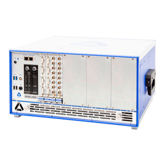
main SyStem Main system Key facts ` Rack-mount or benchtop data acquisition mainframe ` Optional 10 GBit Dual LAN highspeed channel expan- sion ` 4/8/12/16 slots for TRION3/TRION acquisition series modules ` Gapless storage of raw data up to 1 GB/s ` Silent cooling, easy to maintain fan cartridge System specifications DEWE3-RM4... -
Page 13: Overview Of Dewe3-Rmx Series Models
main SyStem DEWE3-RM4 DEWE3-RM8 DEWE3-RM12 DEWE3-RM16 DEWE3-PA8-RM Environmental specifications Operating temperature 0 to +50 °C, down to -20 °C with prewarmed unit Storage temperature -20 to +70 °C Humidity 10 to 80 % non cond., 5 to 95 % rel. humidity Max. -
Page 14: Dewe3-Rm8
main SyStem 8 user-exchangeable slots DEWE3-RM8 12 user-exchangeable slots DEWE3-RM12 16 user-exchangeable slots DEWE3-RM16 Current clamp supply 8 user-exchangeable slots DEWE3-PA8-RM NOTICE Unused TRION slots must always be covered. Make sure to reinstall the filler panels to unused TRION slots to guarantee proper cooling of the installed modules. The warranty is void if the modules overheat due to missing filler panels. -
Page 15: Dimensions
main SyStem Dimensions 434,8 74,7 20,8 20,8 34,2 18,2 390,6 18,2 446,8 Fig. 1: Dimensions DEWE3-RMx / DEWE3-PA8-RM *) Dimensions in mm (1 inch = 25.4 mm) DEWE3-RMx / DEWE3-PA8-RM • Technical reference • Printing version 1.0.3 • May 24, 2023... -
Page 16: Block Diagram
main SyStem Block diagram SYNC bus GBit LAN TRION3/TRION/TRION Timing 4 slot TRION3/TRION PCIe x1 GBit LAN 400 MB/s TRION3 Gen2 TRION3/TRION Backplane TRION3/TRION PCIe x8 Dual 10 GBit LAN Optional feature Gen3 TRION3/TRION 4 slot TRION3/TRION PCIe x1 400 MB/s TRION3 HDMI Gen2... -
Page 17: Connections And Ports
connectionS and PortS Connections and ports 17 17 Fig. 3: Connections and ports DEWE3-RMx / DEWE3-PA8-RM TRION/TRION3 series module slots Power supply input connector TRION SYNC-BUS RS-232 interface connector (COM 1+2) Power on/off push button 13. Dual LAN GBit connectors 10/100/1000 (BaseT Ethernet/ RJ45 connector) EPAD2 connector (LEMO) 14. -
Page 18: Trion/Trion3 Series Module Slots
The power on/off push button at the front of the system is used to switch on the system. It only works if the main pow- er switch (11) on the rear of the instrument is switched to position ‘I’. EPAD2 connector (LEMO) To connect DEWETRON EPAD2 modules to the system, a LEMO EGG.1B.304 socket is provided. Shield is connected on the housing. RS-485 A... -
Page 19: Fan Cartridge
connectionS and PortS Option SSD-256G-1T-EL Upgrade from 256 GB SSD to industrial grade 1 TB SSD with extended life-time 1200 TBW (Tera-Byte Written). Standard SSDs offer typ. 300 to 400 TBW NOTICE Information for systems with SSD drives: Wait for 40 seconds after big files were deleted. The HDD acti- vity LED is lit to indicate that the SSD is deleting the file and TRIM/garbage collection is in progress. -
Page 20: Audio I/O Interface
Linux Ubuntu option (OPT-LINUX) LINUX Ubuntu option for DEWE3 systems Windows Secure Boot Option (OPT-SECURE-BOOT) (DoD-ready) for a new Dewetron system SSD upgrade (SSD-PCIe-1T-2T) Upgrade from 1 TB to 2 TB industrial grade, PCIe attached solid state disk Additional ports for DEWE3-PA8-RM Fig. 6: Additional ports for DEWE3-PA8-RM... -
Page 21: Led Display For Load Of Current Clamps
connectionS and PortS LED display for load of current clamps The 10 segment LED display indicates the load attached to the power supply connectors for current clamps at the rear of the instrument. One LED segment equals 10 %. When exceeding 80 % during active power measurement, consider using an additional DW2-CLAMP-DC-POWER-8 box to split the power (e.g. -
Page 22: Working With The System
Hardware DEWE3/TRION(3) hardware compatibility In 2019, DEWETRON introduced a new family of data acquisition systems, the DEWE3 and TRION3 express series. The DEWE3 chassis feature a PXIe hybrid backplane and supports any TRION3™ series modules. It is also backward compatible and does support all TRION™ series modules from previous generation. -
Page 23: Compatible Sensors/Transducers (Selection)
WorkinG With the SyStem Compatible sensors/transducers (selection) NOTICE Do not use the zero-flux transducer system without power supply. Induction of currents can damage the built-in electronics. NOTICE The maximum cable length from the transducer to the device is 5 m. Longer cable lengths may cause a too high voltage drop. -
Page 24: Trion Series Modules Overview
WorkinG With the SyStem TRION series modules overview Some versions of this module occupy 2 TRION slots CAT III 1000 V only applicable for 1000 V inputs; SUB-600V has CAT II 600 V / CAT III 300 V Analog modules Sample rate Connector Channels... - Page 25 WorkinG With the SyStem Sample rate Channels Resolution Isolation Features DIGITAL modules per channel 100 Hz GNSS 0.01 km/h receiver for auto- TRION-VGPS-V3 2 MS/s 100 Hz <10 cm motive applica- IRIG tions Applies precision TRION-TIMING-V3 2 MS/s 12.5 nsec absolute time to 10 Hz IRIG...
-
Page 26: Installing A Trion Module
WorkinG With the SyStem Installing a TRION module Fig. 7: Installing a TRION module DEWE3 chassis Module guides TRION series module Mounting screws Injector/ejector module In order to install a TRION module into a chassis proceed as follows: Take proper ESD precautions to avoid any damage to the unit. 2. -
Page 27: Star-Slot For Trion Timing/Sync Modules
WorkinG With the SyStem STAR-slot for TRION timing/sync modules 1 Star Fig. 8: STAR-slot for TRION timing/sync modules TRION system timing slot TRION peripheral slot The TRION system timing slot is either slot “1” or labeled as “STAR”. Timing/Sync/GPS modules have to be installed in this slot, but it also accepts any other TRION(3) modules. -
Page 28: Cooling Considerations
WorkinG With the SyStem Right assembly bracket M5x8 M5x8 Left assembly bracket M5x8 M5x8 M5x8 M5x8 M5x8 M5x8 Fig. 10: Installing the 19” mounting brackets NOTICE When installing the 19” mounting brackets, the maximum length for screws is 8 mm. If a screw gets lost, replace it with M5x8 countersunk Phillips head screw only. -
Page 29: System Recovery
WorkinG With the SyStem Installed in a control cabinet, the cool air only travels through the front of the chassis which automatically leads tp a higher fan speed. hot air out min. 1 u (clearance) cool air in DEWE3-RMx installed in a control cabinet hot air out cool air in... -
Page 30: Software
For a more detailed explanation of the OXYGEN software refer to the OXYGEN Technical Reference Manual, which is available at https://ccc.dewetron.com/pl/oxygen. Starting OXYGEN When starting OXYGEN, the measurement screen is displayed. OXYGEN will instantly start to acquire data but will not store it yet. -
Page 31: Changing Channel Settings
WorkinG With the SyStem Fig. 14: Expanding data channel list Changing channel settings The next step is to change the channel settings: 1. Click on the channel name in the list to enter a new name. 2. Alternatively, the channel settings will also open by clicking on the gear button (see Fig. 15). There different settings are available ` Sensor scaling (unit and scaling or sensitivity factor) ` Table scaling for a non-linear scaling... -
Page 32: Design The Measurement Screen
WorkinG With the SyStem Design the measurement screen After the channel settings are done, design the measurement screen to your needs: 1. Double-click/tap on the menu tab or swipe the menu to the right. 2. Click or tap on the Instrument menu tab and drag and drop a recorder on the measurement screen. More instruments can be added and adjusted like this, when being in Design Mode (see 2 in Fig. 13). -
Page 33: Record
WorkinG With the SyStem Record To start the recording proceed as follows. 1. Click on the record button. The red border and the REC indicator seen Fig. 18 in the lower left corner displays, that the recording is going on. 2. Click on the Stop button to stop the recording. The recording process is now finished. - Page 34 WorkinG With the SyStem Fig. 19: Opening data file Fig. 20: Exporting data file for post-processing...
-
Page 35: Synchronization
WorkinG With the SyStem Synchronization Synchronization via TRION-SYNC-BUS The TRION-SYNC-BUS (SYNC IN, SYNC OUT) is used to synchronize two or more DEWE3 systems with up to 100 m dis- tance between each node. The TRION-SYNC-BUS consists of two RJ-45 sockets. One socket is used as synchronization output (OUT), while the other is used as synchronization input (IN). -
Page 36: Gps Sync
WorkinG With the SyStem GPS sync DEWE3-RM16 with TRION-TIMING-V3 or TRION-VGPS module DEWE3-RM16 with TRION-TIMING-V3 or TRION-VGPS module Fig. 22: GPS sync Channel expansion with TRIONet SYNC (max. 100 m) LAN (max 100 m)/USB (max. 1.8 m) for data transfer Fig. 23: Channel expansion with TRIONet... -
Page 37: Network With Multiple Systems
WorkinG With the SyStem Network with multiple systems SYNC (max. 100 m) LAN (max. 100 m) for data transfer Fig. 24: Network with multiple systems Absolute time synchronization With this option, the device can operate synchronized with other measurement devices with an absolute time referen- PTP sync / IRIG sync Synchronization via IRIG DEWE2-M7s with TRION-... -
Page 38: Data Transfer (Independent From Synchronization)
The network topology is the responsibility of the customer. Any topology supported by the operating system can be used. In theory, the normal company network can also be used. However, DEWETRON recommends the use of a sepa- rate network which is only used for data transmission. For data rates beyond 100 Mbyte/s a 10 Gbit option is available which can transfer up to 1 Gbyte/s of data. -
Page 39: Maintenance And Service
Fig. 26: Service intervals DEWETRON offers various service and upgrade plans including cleaning/exchanging fans/power supply/CPU cooler (if required), BIOS, firmware and driver updates as well as reliabilty upgrades and full functionality check. Ask DEWETRON or your local distributor for further information and pricing. -
Page 40: Removing The Fan Cartridge And Cleaning The Filter Pad
maintenance and Service Removing the fan cartridge and cleaning the filter pad Requirements ` TORX T10 screw driver ` Nut driver with a hexagonal socket (7 mm) WARNING Do not attempt to remove filter covering plate when in operation. Warranty void if the modules overheat by removing the fan cartridge when in operation. Power off the instrument and disconnect the device from the power supply first. - Page 41 maintenance and Service 5. Loosen the screws on both sides with a TORX T8 screwdriver. 6. To release, slightly raise the protective grille and pull it out afterwards. Use a dry velocity stream of air to clean the fans and the filter pad. 7.
-
Page 42: Removing The Feet For Control Cabinet Installation
Any change in the file structure as deleting or adding files or directories might cause a system crash. Before installing software updates contact DEWETRON or your local distributor. Use only software packages which are released by DEWETRON. Further information is also available in the Internet (http:// www.dewetron.com). -
Page 43: Windows And Antivirus/Security Software
08:00 and 16:30 EST Service and repairs We are very sorry that your DEWETRON system is not operating properly. Our team is here to ensure that your DEWE- TRON product is returned to peak performance as quickly as possible. Help us to provide you with the best support by following the RMA policy. - Page 44 Products arriving at our repair department without RMA require follow-up calls and investigation, which lead to a longer turnaround. Only the team of DEWETRON is allowed to perform any kinds of repairs to your system to assure a safe and proper operation in future.
-
Page 45: Letter Of Volatility
Data drive Solid State Drive 5220.22-M wiping BIOS Chip EEPROM 32 MB BIOS Settings, firmware Factory reset Read only, yes under DEWETRON Explorer Flash 16 MB Chassis controller firmware certain circumstances firmware update Tab. 9: Non-volatile memory Radio communication This measuring instrument does not include any integrated radio communication technology, such as Wi-Fi or Blue- tooth. -
Page 46: Certificate Of Conformity
CE certificate of conformity DEWE3-RMx Manufacturer DEWETRON GmbH Address Parkring 4 8074 Grambach, Austria Tel.: +43 316 3070-0 Fax: +43 316 3070-90 Email: sales@dewetron.com http://www.dewetron.com DEWE3-RMx Name of product Kind of product Rack-mount data acquisition instrument The product meets the regulations of the following EC-directives:... -
Page 47: Ce Certificate Of Conformity Dewe3-Pa8-Rm
CERTIFICATE OF CONFORMITY CE certificate of conformity DEWE3-PA8-RM Manufacturer DEWETRON GmbH Address Parkring 4 8074 Grambach, Austria Tel.: +43 316 3070-0 Fax: +43 316 3070-90 Email: sales@dewetron.com http://www.dewetron.com DEWE3-PA8-RM Name of product Kind of product Rack-mount data acquisition instrument The product meets the regulations of the following EC-directives:... -
Page 48: Conformity To Iec 61000-4-30
Conformity to IEC 61000-4-30 Conformity to IEC 61000-4-30 Manufacturer DEWETRON GmbH Address Parkring 4 8074 Grambach, Austria Tel.: +43 316 3070-0 Fax: +43 316 3070-90 Email: sales@dewetron.com htt p://www.dewetron.com This certi fi cate has been issued as a result of an assessment of the performance of the models listed below as to their conformity with the requirements of IEC 61000-4-30:2008 Class A, Electromagneti c compati bility (EMC) Part 4-30: Testi ng and measurement techniques –...
Need help?
Do you have a question about the DEWE3-RM Series and is the answer not in the manual?
Questions and answers