Table of Contents
Advertisement
Quick Links
DEWE-ORION-1616-10x
TECHNICAL REFERENCE MANUAL
WELCOME TO
THE WORLD OF
DEWETRON!
Congratulations on your new device! It
will supply you with accurate, complete
and reproducible measurement results
for your decision making.
ISO9001
Look forward to the easy handling and
the flexible and modular use of your
DEWETRON product and draw upon
more than 30 years of DEWETRON ex-
EN ISO 14001
pertise in measurement engineering.
THE MEASURABLE DIFFERENCE.
Advertisement
Table of Contents

Subscribe to Our Youtube Channel
Related Manuals for Dewetron DEWE-ORION-1616-10 Series


Summary of Contents for Dewetron DEWE-ORION-1616-10 Series
- Page 1 ISO9001 Look forward to the easy handling and the flexible and modular use of your DEWETRON product and draw upon more than 30 years of DEWETRON ex- EN ISO 14001 pertise in measurement engineering. THE MEASURABLE DIFFERENCE.
- Page 2 Copyright © DEWETRON elektronische Messgeraete Ges.m.b.H. This document contains information which is protected by copyright. All rights are reserved. Reproduction, adaptation, or translation without prior written permission is prohibited, except as allowed under the copyright laws. All trademarks and registered trademarks are acknowledged to be the property of their owners.
-
Page 3: Table Of Contents
General Information, Safety Instructions Warranty Information ……………………………………………………………………… 5 Support ……………………………………………………………………………………… 5 Printing History ……………………………………………………………………………… 5 Safety symbols in the manual …………………………………………………………… 6 Safety instructions for all DEWETRON DAQ boards …………………………………… 7 Environmental Considerations …………………………………………………………… 8 Product End-of-Life Handling …………………………………………………………………………………8 System and Components Recycling …………………………………………………………………………8... - Page 4 Table of content 3 Theory of operation …………………………………………………………………… 37 3.1 Analog input ………………………………………………………………………………………… 37 3.1.1 Analog input circuit ………………………………………………………………………………………37 3.1.2 Analog to digital conversion ……………………………………………………………………………37 3.1.3 Output data format ………………………………………………………………………………………37 3.1.4 Calibration …………………………………………………………………………………………………37 3.2 Counter input ……………………………………………………………………………………… 38 3.2.1 Counter applications ………………………………………………………………………………………38 3.2.1.1 Event Counting ………………………………………………………………………………………………...
-
Page 5: General Information, Safety Instructions
THE IMPLIED WARRANTIES OF MERCHANTABILITY AND FITNESS FOR A PARTICULAR PURPOSE. DEWETRON shall not be liable for any direct, indirect, special, incidental, or consequential damages, whether based on contract, tort, or any other legal theory, in connection with the furnishing of this document or the use of the information in this document. -
Page 6: Safety Symbols In The Manual
Failure to comply with these precautions or with specific warnings elsewhere in this manual violates safety standards of design, manufacture, and intended use of the product. DEWETRON Elektronische Messgeraete Ges.m.b.H. assumes no liability for the customer’s failure to comply with these requirements. -
Page 7: Safety Instructions For All Dewetron Daq Boards
Safety instructions Safety instructions for all DEWETRON DAQ boards The DEWETRON data acquisition boards may only be installed by experts. Read your manual before operating the board. Observe local laws when using the board. DO NOT operate the product in an explosive atmosphere or in the presence of flammable gases or fumes. DO NOT operate damaged equipment: Whenever it is possible that the safety protection features built... -
Page 8: Environmental Considerations
Environmental Considerations Information about the environmental impact of the product. Product End-of-Life Handling Observe the following guidelines when recycling a DEWETRON system: System and Components Recycling Production of this components required the extraction and use of natural resources. The substances... -
Page 9: Dewe-Orion-1616-10X
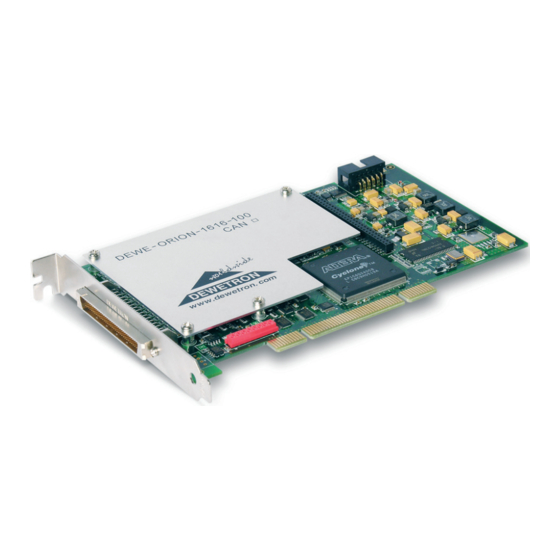
The DEWE-ORION-1616-10x series expands the simultaneous sample A/D-boards from DEWETRON. Even the standard version offers already 16 analog input channels, two 32-bit counter/encoder inputs and 16 digital inputs - 8 of them can also be used for outputs. The onboard RS-485 interface controls DEWETRON signal conditioning amplifiers and can directly acquire data from PAD/EPAD series modules. -
Page 10: Requirements For Using The Dewe-Orion-1616-10X
WINDOWS 2000 or XP operating system DEWE-ORION-1616-10x board DEWE-ORION-1616-10x Technical Reference Manual (shipped with the board or available on www.dewetron.com or ftp.dewetron.com) Device driver (shipped with the board) Recommended options (not shipped with the board): Signal connection (e.g. BNC connector box ORION-CB16-BNC) DEWESoft 6 (or higher) or other application software 1.5 Unpacking... -
Page 11: Using Dewe-Orion-1616-10X
Chancel the windows hardware-driver wizard. IInsert the DEWE-System DVD shipped together with the board into your DVD drive (for example D:\) and start the following executable file: D:\Install\Drivers\6_DaqBoards\Dewetron\OrionDAQ\OrionSetup.exe. After the installation you have to reboot the system. Page 11... -
Page 12: Software Installation
DEWE-ORION-1616-10x 2.2 Software installation 2.2.1 DEWESoft installation If the installation software doesn’t start when you insert the DEWE-System DVD into the computer, start it manually by clicking on the ShelExec.exe file on the DVD or navigate to “HTML” and start the index.html. Follow the instructions of the installer. Page 12... - Page 13 DEWE-ORION-1616-10x The install shield wizard will simplify the installing procedure. Select the needed options you want to install and enter your information. Select the features you want to install and start the installation. Page 13 DE-M060304E • DEWE-ORION-1616-10x • Technical Reference Manual • Printing version 1.2.0 • March 19, 2014...
- Page 14 You can start the software in the Windows start menu or use the icon created on your desktop. For more information about the DEWESoft installation please refer to the DEWESoft Software Users Manual. To modify the hardware settings, select System - Hardware setup in the menu. Select DEWETRON DAQ at the analog device selection field and enter your username, user location and registration code. You can find them in your DEWESoft licence agreement.
-
Page 15: Connecting Signals
DEWE-ORION-1616-10x 2.3 Connecting signals 2.3.1 Naming In multiple board systems a clear defined channel name structure is important to avoid inconstancy in the channel connection. Usually analog input channels are just named in a row. Therefore at a 3 board system the channels are named from CH 0 to CH 47. Due to the flexible structure of the digital and counter inputs the naming in a row is not possible. That’s why each input at the ORION base board (code letter B) and also at the expansion board (code letter E) gets a channel prefix name like shown in the example below for a two board system. -
Page 16: Connectors
Counter Digital For easy access to the digital and counter inputs Input Input Input Input DEWETRON instruments are equipped with a DB37 connector for board 0. Also all hardware synchronisation Bx_DI 8 Bx_DO 0 DGND Bx_DI 9 Bx_DO 1 signals (for example clocking the camera, syncronisation... -
Page 17: Connectors For Ttl Counter Expansion
DEWE-ORION-1616-10x Optional ORION-CNT2-LEMO As an option (ORION-CNT2-LEMO) the two counters can be also wired to a 7-pin female lemo connector for direct connection of encoders or any other counter channel source. 1: Source Bx_CNT(n) 2: Aux_Bx_CNT(n) 3: Gate Bx_CNT(n) 4: Power GND 5: +5 V (max. -
Page 18: Signal Connection For Ttl Counter Expansion
DEWE-ORION-1616-10x 2.3.2.4 Signal connection for TTL counter expansion Without any option the counter or digital inputs are wired to a 68 pin female connector on DEWETRON instruments. An easy sensor connection possibility is given with ORION-CB-CNT8 connection box. For direct connection of the sensor to the instrument various options for counter panels are available: ORION-DIO-PANEL-1 These panels should be used if mainly counter/encoder signals will be measured. - Page 19 DEWE-ORION-1616-10x Isolated DB37 pinout for ORION-DIO-PANEL-3 Digital Counter Digital Counter Input Input Input Input In+ (DI 0) In+ (DI 16) In- (Ex_DI 16) In- (Ex_DI 0) In+ (DI 1) In+ (DI 17) Aux Ex_CNT5 In- (Ex_DI 17) In- (Ex_DI 1) In+ (DI 2) In+ (DI 18) Gate_Ex_CNT5...
-
Page 20: Connectors For Adjustable Counter Expansion
(AMP: 174339-5) SCSI II 2.3.2.6 Adapters for adjustable counter expansion Without any option the counter or digital inputs are wired to a 68 pin female connector on DEWETRON instruments. An easy sensor connection possibility is given with ORION-CB-CNT8 connection box. - Page 21 DEWE-ORION-1616-10x Non isolated DB37 pinout for ORION-DIO-PANEL-1 and ORION-DIO-PANEL-2 Digital Counter Digital Digital Counter Digital Input Input Input Input Input Input Ex_DI 0 Ex_DI 16 DGND DGND Ex_DI 1 Ex_DI 17 Aux Ex_CNT5 DGND DGND Ex_DI 2 Ex_DI 18 Gate_Ex_CNT5 DGND DGND Ex_DI 3...
-
Page 22: Connectors For Analog Expansion
DEWE-ORION-1616-10x DEWE-ORION-1616-104 ORION-DIO-PANEL-1: BOX-ORION-CB- ORION-DIO-PANEL-2: with ORION-EXP-CNT8- 8 counter inputs wired to CNT8 for easy sensor 2 counter inputs wired ADJ board 7-pin LEMO connectors connection to LEMO and 32 digital inputs wired to SUB-D connectors 2.3.2.7 Connectors for analog expansion Analog expansion The analog expansion connector supports no counter Digital... -
Page 23: Internal Synchronisation Connector
DEWE-ORION-1616-10x Pin assignment of the 9-pin connectors on the DB9-adaptor. Res. +12 V Res. Res. DGND CANx_high CANx_low DGND +5 V 9-pin SUB-D connector male Two 9-pin SUB-D connectors prepared to be mounted inside systems DEWE-CAN-CAB-2 with two 9-pin SUB-D connectors Pin assignment of the on-board 7-pin Lemo connector CAN1_low +5 V... -
Page 24: Analog Signals
DEWE-ORION-1616-10x 2.4 Analog signals The block diagram below (figure 1) gives an idea of the analog input configuration. The DEWE-ORION-1616-10x consists of 16 separate input amplifiers and analog to digital converters. Each input has four different gains for getting the input voltage range from ±1.25 V to ±10 V. ADC 0 ADC 8 CH 0+ CH 8+ ADC 1 ADC 9 CH 1+ CH 9+ ADC x ADC x CH x+ CH x+... -
Page 25: Counter And Digital I/O
DEWE-ORION-1616-10x The input voltage range in sensed mode is limited to ±12 V. The voltage level of the sense input is the same like the current set input voltage range. Example for input range ±5 V Ch x = +8 V, Sense = 4 V, voltage difference = 4 V, result is valid Ch x = +10 V, Sense = 6 V, voltage difference = 4 V, result is not valid (the input voltage is less than 12 V but the sense voltage level (6 V) is higher than the input range. -
Page 26: Basic Counter Organisation
DEWE-ORION-1616-10x 2.5.2 Basic counter organisation Figure 3 shows the principal of a counter block. The counter consists of 4 inputs. The input “Armed” is need- ed for starting and triggering the counter. The basic input of a counter is the source pin. The default usage of this input is event counting. -
Page 27: Counter And Di/O Dewe-Orion-1616-100/101
DEWE-ORION-1616-10x 2.5.3 Counter and DI/O DEWE-ORION-1616-100/101 The counters and digital input and output at the DEWE-ORION-1616-100 can be configured in the most flex- ible way. DI0 to DI7 can be used as digital input and / or for the counter inputs. Please refer also to the input connector description above. Source Bx_CNT0 ~ 1 Filter Counter 0 Counter out 0 Gate Bx_CNT0 ~ 1 Decoder... -
Page 28: Counter And Di/O Dewe-Orion-1616-102/103
DEWE-ORION-1616-10x 2.5.4 Counter and DI/O DEWE-ORION-1616-102/103 The number of counters and digital inputs can be expanded with the counter expansion add-on board. All the baseboard functionality stays the same like in the standard configuration. Similar to the counter inputs of DEWE-ORION-1616-100/101, the input pins can also share the function for digital inputs or counter inputs. Please also refer to the pin-out description in chapter 2.3.1. The block diagram (figure 6) indicates that eight counter channels and theoretically 16 digital inputs can be transferred at once. -
Page 29: Counter And Di/O Dewe-Orion-1616-104/105
DEWE-ORION-1616-10x The output settings can be done inside the hardware setup of DEWESoft. 2.5.5 Counter and DI/O DEWE-ORION-1616-104/105 Similar to DEWE-ORION-1616-102/103 this board provides eight counter channels and up to 32 digital inputs where the input pins can share this functionality. The difference is just the electrical input circuit. - Page 30 DEWE-ORION-1616-10x Signal DC coupled Signal AC coupled TrigLevel RetrigLevel 0 Logic Time [ms] The levels can be set for each input independent like shown on the next picture. Some common used levels are predefined (like TTL, inductive pick-up sensors…). Selecting “Custom” as the trigger type. All parameters are free definable. If the sensor signal is not known, an automatic algorithm for finding the trigger levels is implemented. A sensor like the shown encoder has usually for all outputs the same signal level. Enabling “trigger settings same for all lines”...
-
Page 31: Clock And Trigger I/O
DEWE-ORION-1616-10x 2.6 Clock and trigger I/O The DEWE-ORION-1616-10x allows external triggering for start of the acquisition using the pin EXT_Trigger. The default detection for the trigger signal is the rising edge but can be configured to falling or both edge (change of input signal) detection. Changing the direction to output, the start of acquisition can be indicated. EXT_CLKx are used as standard for hardware synchronization to DEWE-CAM, CAN or 3 party hardware. Each output can set individually. The predefined settings are: Video: The output frequency is automatically set to the frame rate of the selected video device. If no camera is selected, the output is disabled CAN: The signal is automatically set for hardware synchronisation of NI-CAN device. - Page 32 DEWE-ORION-1616-10x The output of all slave board is switched off. The diagram below gives an idea of the internal structure of EXT_CLKx and EXT_Trigger circuit: EXT_CLKx internal signal: ADC sample clock or 80 MHz DIR_CLK EXT_Trigger internal signal: start of acquisition DIR_Trigger EXT_CLK1 internal signal: CLK1 I/O DIR_CLK1 EXT_CLK2 internal signal: CLK2 I/O DIR_CLK2 Figure 7: Clock and trigger I/O configuration The direction (input or output) of each pin can be switched separately.
-
Page 33: Can Interface
2.8 RS-485 interface The DEWE-ORION-1616-10x is suited with an RS-485 interfaced as standard. The baud-rate is fixed to 9600, 8 Data, 1 Stop bit and no parity. This interface is used for configuration of the DAQ and MDAQ signal conditioning modules. Also the acquiring of PAD and EPAD from DEWETRON is possible with this RS-485 port. The interface of the main board and the expansion boards (DEWE-ORION-1616-102 with counter ex- pansion) is controlled separately. -
Page 34: Synchronizing Multiple Boards
50 metres by using standard CAT5 Ethernet cables. Please contact DEWETRON if longer synchronization distance is required! The ORION-1616-SYNCH also includes the security circuit if two master systems have to be connected together over the synch bus connection. As soon as the system is configured to a master system the external... -
Page 35: Defining The Board Order
DEWE-ORION-1616-10x Optocoupler emitter Opto collector Sys-on Synch in Power +5 V Power GND ME / MI indication Synch out To DEWE-ORION-1616-10x Synchbus ORION-1616-SYNCH In addition to the synchronization function the ORION-1616-SYNCH allows also to remote power the slave system. As soon as a master system is present a opto coupler output (PC817) is activated to switch on the power supply. - Page 36 DEWE-ORION-1616-10x Click on "driver details" to get the next screen ORION cards in automatic order The order can be changed by clicking on the name of the board and moving it with the move up/down but- tons. Please note that the settings are taken only after clicking the button <Apply>. A click on the <Refresh> button shows the actual settings.
-
Page 37: Theory Of Operation
3.1.4 Calibration Your DEWE-ORION-1616-10x is shipped with a calibration certificate. Typically a recalibration is required every year. The calibration constants are stored in the on-board EEPROM. The calibration can only be done with an optional available calibration kit or you can send the DEWE-ORION-1616-10x back to DEWETRON for recalibration. Page 37 DE-M060304E • DEWE-ORION-1616-10x • Technical Reference Manual • Printing version 1.2.0 • March 19, 2014... -
Page 38: Counter Input
DEWE-ORION-1616-10x 3.2 Counter input 3.2.1 Counter applications As mentioned above each counter block is equipped with three inputs. With this three inputs the following applications can be done: • Event Counting • Gated Event Counting • Up/Down Counter • Frequency Measurement •... -
Page 39: Gated Event Counting
DEWE-ORION-1616-10x 3.2.1.2 Gated Event Counting Gated Event Counting is similar to Event Counting except that the counting process is gated. When Counter Gate is active, the counter counts pulses which occur on counter source. When Counter Gate is inactive the counter retains the current count value. -
Page 40: Up/Down Counter
DEWE-ORION-1616-10x 3.2.1.3 Up/Down Counter The Up/Down Counter counts the rising edges on Counter Source. The direction of the counting depends on the signal state on Counter Aux. If Counter Aux is active (high level), the counter is increasing the counter value;... -
Page 41: Period Time Measurement
DEWE-ORION-1616-10x 3.2.1.4 Period Time Measurement In Period Time Measurement the counter uses the internal time base to measure the period time of the signal present on Counter Source. The counter counts the rising edges of the internal time base which occurs between two rising edges on Counter Source. -
Page 42: Two Pulse Edge Separation Measurement
DEWE-ORION-1616-10x Sample Clock Counter Source 80 MHz Counter Value 144 144 72 72 1309 1309 Synchronized Value Figure 16: Pulse Width Measurement For measuring the low time of the signal, the input signal has to be inverted on the ORION-EXP-CNT6. 3.2.1.6 Two Pulse Edge Separation Measurement The two pulse edge separation measurement is similar to the pulse width measurement, except that there are two input signals: Counter Start and Counter Stop. -
Page 43: Motion Encoder
DEWE-ORION-1616-10x Figure 17 shows an example of Two Pulse Edge Separation Measurement. Sample Clock Counter Start Counter Stop 80 MHz Counter Value 1260 218 145 1648 Synchronized Value 1260 1648 Figure 17: Two Pulse Edge Separation Measurement If the input signals are inverted the counter takes the falling edges for counting. 3.2.1.7 Motion Encoder Motion encoders have usually three channels: channel A, B and Z. -
Page 44: Quadrature Encoder
DEWE-ORION-1616-10x 3.2.1.8 Quadrature Encoder In the first case X1 decoding is explained. When Input A leads Input B in a quadrature cycle, the counter increments on rising edges of Input A. When Input B leads Input A in a quadrature cycle, the counter decre- ments on the falling edges of Input A. At every Sample Clock ( , …, ) the counter value is read out. - Page 45 DEWE-ORION-1616-10x Figure 20 shows the results for X4 encoding. Sample Clock Input A Input B Counter Value 3 4 5 6 7 8 17 16 Synchronized Value Figure 20: Quadrature Encoder X4 Mode The third channel Input Z, which is also referred as the index channel, causes the counter to be reloaded with zero in a specific phase of the quadrature cycle.
-
Page 46: A-Up/B-Down Encoder
DEWE-ORION-1616-10x 3.2.1.9 A-Up/B-Down Encoder The A-Up/B-Down Encoder supports two inputs, A and B. A pulse on Input A increments the counter on its rising edges. A pulse on Input B decrements the counter on its rising edges. At every Sample Clock ( …, ) the counter value is read out. -
Page 47: Frequency Measurement
DEWE-ORION-1616-10x 3.2.1.10 Frequency Measurement In general it is possible to take the inverse of a period measurement to get the frequency of the input signal. If the period time measurement is done an inaccuracy of counted internal time base cycles of ±1 cycle ap- pears, because the counted cycles of the internal time base depends on the phase of the input signal with re- spect to the internal time base. -
Page 48: Miscellaneous Counter Functions
DEWE-ORION-1616-10x sample clock counter source real counter value ORION counter standard counter For low frequency input signals the frequency also can be obtained by measure the period time and take its inverse without more inaccuracy. 3.2.2 Miscellaneous counter functions 3.2.2.1 Filters Each counter input has a digital filter, which can be set to various gate times. If the gate time is set to “Off”, no filter is on the input signal. -
Page 49: Reset On Start Measure
DEWE-ORION-1616-10x Internal Time Base (80MHz) Filter Input Signal Filter Output Signal Gate Time Gate Time Figure 25: Input signal with chatter It can be chosen between eight filter settings: Off, 100 ns, 200 ns, 500 ns, 1 µs, 2 µs, 4 µs and 5 µs. Two examples of filter settings are described. The 100 ns filter will pass all pulse widths (high and low) that are 100 ns or longer. It will block all pulse widths that are 75 ns or shorter. The 5 µs filter will pass all pulse widths (high and low) that are 5 µs or longer and will block all pulse widths that are 4.975 µs or shorter. The internal sampling clock (time base) is 80 MHz, so the period time amounts 12.5 ns. Pulse widths be- tween gate time minus two internal time base period times may or may not pass, depending on the phase of the input signal with respect to the internal time base. -
Page 50: Count Direction
DEWE-ORION-1616-10x 3.2.2.3 Count Direction As default setting the count direction is in up-counting mode. Every rising edge at the input will increase the counter value. The DEWE-ORION-1616-10x supports also down counting without the need of an additional input like in the up/down counting mode. 3.2.2.4 No new value available Especially in every kind of input period time measurement mode (also pulse width or two pulse edge separation measurement) there may be new information between two samples. -
Page 51: Specifications
DEWE-ORION-1616-10x 4 Specifications 4.1 Analog input Analog input Channel characteristics Number of channels 16 (or 32) simultaneously sampled Input configuration single ended with remote sense Resolution 16-bit Effectiv number of bits 14,7 Type of ADC Successive approximation (SAR) Sampling rate 1 to 100 kS/s per channel Sampling rate accuracy 35 ppm... -
Page 52: Digital And Counter Input
DEWE-ORION-1616-10x 4.2 Digital and Counter input Digital and Counter input Counter resolution 32-bit Counter time base 80 MHz Time base accuracy 35 ppm Maximum input frequency 40 MHz Input signal characteristic main board Compatibility TTL/CMOS Configuration Pull-up with 100 kOhm Input low level -0.7 V to 0.8 V Input high level... -
Page 53: Digital And Clock Divider Output
DEWE-ORION-1616-10x 4.3 Digital and clock divider output Digital and clock divider out Compatibility TTL/CMOS Characteristic Low voltage level < 0.4 V @ 4 mA load High voltage level > 3 V @ 4 mA load Output current Sink (low level) -20 mA Source (high level) 20 mA... - Page 54 DEWE-ORION-1616-10x General Specifications General Specifications Environmental Operating temperature 0 to 50 °C Storage temperature -20 to 70 °C Relative humidity 10 to 90%, non condensing Maximum altitude 2000 m Pollution degree (indoor use only) Physical Dimensions (not including connectors) 17.5 x 10.7 cm (6.9 x 4.2 in.) Analog input connector (main board) 68-pin SCSI male (AMP 174341-5) Analog input connector (expansion)
- Page 55 CE-Certificate of conformity CE-Certificate of conformity Manufacturer: DEWETRON Elektronische Messgeraete Ges.m.b.H. Address: Parkring 4 A-8074 Graz-Grambach Austria Tel.: +43 316 3070 0 Fax: +43 316 3070 90 e-mail: sales@dewetron.com http://www.dewetron.com DEWE-ORION-1616-10x Name of product: Kind of product: A/D board The product meets the regulations of the following EC-directives: 73/23/EEC "Directive on the approximation of the laws of the Member States relating to...
- Page 56 Notes...
Need help?
Do you have a question about the DEWE-ORION-1616-10 Series and is the answer not in the manual?
Questions and answers