Table of Contents
Advertisement
Quick Links
Advertisement
Table of Contents

Subscribe to Our Youtube Channel
Related Manuals for Dewetron DEWE-30-32


Summary of Contents for Dewetron DEWE-30-32
- Page 1 A u t o m o t i v e E n e r g y & P o w e r A n a l y s i s A e r o s p a c e & D e f e n s e T r a n s p o r t a t i o n G e n e r a l T e s t &...
- Page 2 Copyright © DEWETRON elektronische Messgeraete Ges.m.b.H. This document contains information which is protected by copyright. All rights are reserved. Reproduction, adaptation, or translation without prior written permission is prohibited, except as allowed under the copyright laws. All trademarks and registered trademarks are acknowledged to be the property of their owners.
- Page 3 BNC connectors (± 50V max.), D-SUB connectors (± 50V max.), thermocouple connectors (± 50V max.), BINDER connectors (± 50V max.), SMB connetcors (± 50V max.), µdot connectors (± 50V max.), ® LEMO connectors or RJ-45 connectors. ® DE-M071102E • DEWE-30-32 • Technical Reference Manual • Printing version 1.1.1 • June 12, 2013...
- Page 4 Preface Notes...
-
Page 5: Table Of Contents
Option 30-32-DIFF-OUT (differential output) …………………………………………… 20 Bandwidth …………………………………………………………………………………… 24 Option 30-HSI ……………………………………………………………………………… 25 Option 30-32-DC …………………………………………………………………………… 25 Software A/D Conversion Internal Wiring CE-Certificate of conformity DE-M071102E • DEWE-30-32 • Technical Reference Manual • Printing version 1.1.1 • June 12, 2013... - Page 6 Table of content...
-
Page 7: General Information, Safety Instructions
Support DEWETRON has a team of people ready to assist you if you have any questions or any technical difficulties regarding the system. For any support please contact your local distributor first or DEWETRON directly. For Asia and Europe, please contact: For the Americas, please contact: DEWETRON Ges.m.b.H. -
Page 8: Warranty Information
Warranty Information A copy of the specific warranty terms applicable to your DEWETRON product and replacement parts can be obtained from your local sales and service office. Restricted Rights Legend Use austrian law for duplication or disclosure. -
Page 9: Safety Symbols In The Manual
For safety reasons max. 50 V may be applied to the BNC input-connectors! Refer to the regulation of maximum allowable touch potential. DE-M071102E • DEWE-30-32 • Technical Reference Manual • Printing version 1.1.1 • June 12, 2013... -
Page 10: General Safety And Hazard Warnings For All Dewetron Systems
Safety instructions Your safety is our primary concern! Please be safe! General safety and hazard warnings for all DEWETRON systems Use this system under the terms of the specifications only to avoid any possible danger. Maintenance will be executed by qualified staff only. - Page 11 The electrical installations and equipments in industrial facilities must be observed by the security regulations and insurance institutions. DE-M071102E • DEWE-30-32 • Technical Reference Manual • Printing version 1.1.1 • June 12, 2013...
- Page 12 Safety instructions The use of the measuring system in schools and other training facilities must be observerd by skilled personnel. The measuring systems are not designed for use at humans and animals. Please contact a professional if you have doubts about the method of operation, safety or the connection of the system.
-
Page 13: Windows Updates And Antivirus/Security Software
Problematic network stacks Often intrusive IT software or network processes can interfere with the primary function of the DEWETRON system: to record data. Therefore we recommend strongly against the installation of IT/MIS software and running their processes on any DEWETRON data acquisition system, and cannot guarantee the performance of our systems if they are so configured. -
Page 14: First Steps
First steps First steps Power-on your system. Connect your sensors to the system. Run DEWESoft usually via "Start" >"Programs" > "Dewetron" > "DEWESoft x.x" > "DEWESoft x.x" Start recording your data! -
Page 15: Main System
Please check the appropriate modules manual for power consumption of each installed module and calculate the total power consumption. Derating 0.9 W/°C above 40 °C for AC power supply DE-M071102E • DEWE-30-32 • Technical Reference Manual • Printing version 1.1.1 • June 12, 2013... -
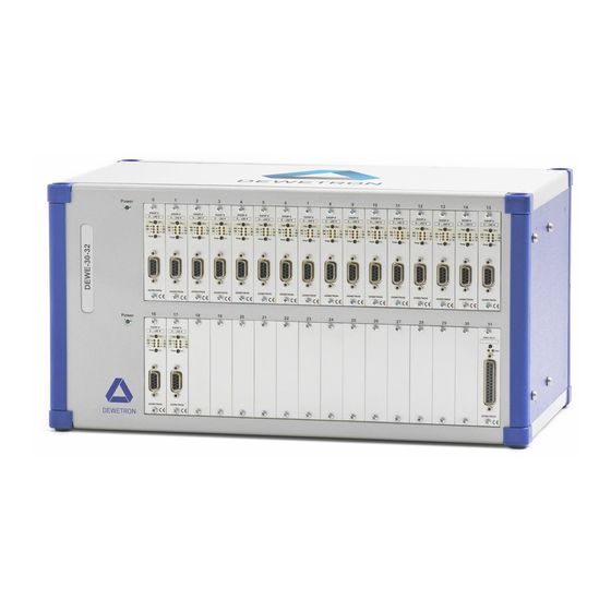
Page 16: Dewe-30-32 At A Glance
Dimensions* with 19“ mounting kit 481,6 * Dimensions in mm (1 inch = 25.4 mm) DEWE-30-32 at a glance 1 68-pin SUB-D socket for conditioned Typical DEWE-30-32 rear view signal output 2 RS-485 In/Out (EPAD) 3 to PC COM port, RS-232... - Page 17 AI 3 AI 2 AI 10 AI 9 AI GND AI GND AI 1 AI 0 AI 8 68-pin Amplimite series (AMP: 174339-5) SCSI II DE-M071102E • DEWE-30-32 • Technical Reference Manual • Printing version 1.1.1 • June 12, 2013...
- Page 18 Main System RS-485 In/Out (EPAD) To connect DEWETRON EPAD modules to the system. Pin assignment 8 7 6 5 4 3 2 1 1: RS-485 A 2: RS-485 B 14: GND (power supply EPAD modules) 15 14 13 12 11 10 9...
- Page 19 This connector supports standard 100 .. 250 V power supply input for your system. Power-on switch The power-on switch has to be used to switch on the system. Ground switch DE-M071102E • DEWE-30-32 • Technical Reference Manual • Printing version 1.1.1 • June 12, 2013...
-
Page 20: Option 30-32-Diff-Out (Differential Output)
Main System Option 30-32-DIFF-OUT (differential output) 32 channel to balanced differential output High output current of ±60 mA Stable with high capacitive load of 50 nF Short circuit proofed output Bandwidth up to 1 MHz Replaces 68-pin female SUB-D with 37-pin female SUB-D connectors Specifications 30-32-DIFF-OUT ±5 V (±2.5 V referenced to GND) - Page 21 Sensor Input Connection depends on Switch on DEWE-30-xx rear panel power supply configuration for connecting amplifier GND (see text above) to the housing (personal earth) DE-M071102E • DEWE-30-32 • Technical Reference Manual • Printing version 1.1.1 • June 12, 2013...
- Page 22 Main System Bandwidth and cable length Although the bandwidth of the 30-32-DIFF-OUT amplifier itself is above 1 MHz the total reached bandwidth is depending on the used cable length. The longer the cable the lower the efficient bandwidth. The reason is the parasite cable capacitance which is around 30-200 pF per meter.
- Page 23 3: GND n.c. 4: n.c. n.c. 15 14 13 12 11 10 9 5: GND n.c. 6: n.c. n.c. 7: GND +12 V fused (1A) DE-M071102E • DEWE-30-32 • Technical Reference Manual • Printing version 1.1.1 • June 12, 2013...
-
Page 24: Bandwidth
Bandwidth Standard DEWE-30-32 configuration 300 kHz standard no bandwidth limitation with 30-HSI option HSI ready by option 30-HSI DEWE-30-32 with option DEWE-30-OUT-5 300 kHz no bandwidth limitation with 30-HSI option HSI ready option DEWE-30-OUT-5 by option 30-HSI DEWE-30-32 with option DEWE-30-OUT-10... -
Page 25: Option 30-Hsi
This connector is only available with option 30-32-DC. The DC power supply (9 .. 40 V ) replaces the standard AC power supply, incl. 2 m DC connection cable with banana jacks. DE-M071102E • DEWE-30-32 • Technical Reference Manual • Printing version 1.1.1 • June 12, 2013... - Page 26 Main System Notes...
-
Page 27: Software
Another important new feature is the sequencer which provides a way to automate test procedures. DE-M071102E • DEWE-30-32 • Technical Reference Manual • Printing version 1.1.1 • June 12, 2013... - Page 28 DEWETRON hardware cards as well as some third-party cards, like Spectrum cards for ™ transient recording. Multiple cards of the same family are supported for high channel counts. There is also a huge range of DEWETRON signal conditioners which are all perfectly implemented into the soft- ware. Besides the analog inputs DEWESoft supports the digital I/Os, counters and CAN interfaces of DEWETRON ™...
- Page 29 This allows you to work with the data as you were at the test bench or on the proving ground. DE-M071102E • DEWE-30-32 • Technical Reference Manual • Printing version 1.1.1 • June 12, 2013...
- Page 30 DEWESoft ™ Notes...
-
Page 31: A/D Conversion A1
Please find information about the A/D conversion in the attached DEWE-ORION series manual. The latest version of the manual can be downloaded from: http://download.dewetron.com/dl/components/adboards Informations regarding different manufacturer's see the corresponding D/A card manual. DE-M071102E • DEWE-30-32 • Technical Reference Manual • Printing version 1.1.1 • June 12, 2013... - Page 32 A/D & D/A Conversion Notes...
-
Page 33: Internal Wiring B1
9-pin SUB-D connector reserved -9 V power supply The 16 slot DEWE-MOTHERBOARD receives the ±12 V power supply via a DC/DC converter from the internal power supply. DE-M071102E • DEWE-30-32 • Technical Reference Manual • Printing version 1.1.1 • June 12, 2013... - Page 34 Internal Wiring Notes...
- Page 35 EN 55011 Class B Immunity EN 61000-6-2 Group standard Graz, April 28, 2010 Dipl.-Ing. Roland Jeutter / Managing director Place / Date of the CE-marking DE-M071102E • DEWE-30-32 • Technical Reference Manual • Printing version 1.1.1 • June 12, 2013...
- Page 36 Notes...
Need help?
Do you have a question about the DEWE-30-32 and is the answer not in the manual?
Questions and answers