Table of Contents
Advertisement
Quick Links
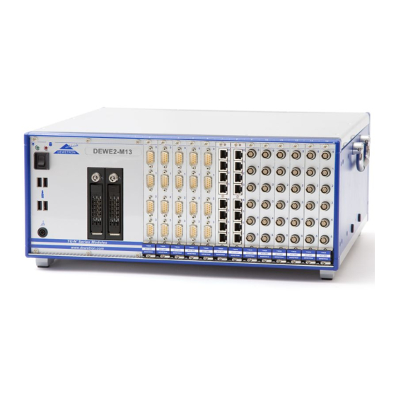
DEWE2-M13
TECHNICAL
REFERENCE
MANUAL
WELCOME TO
THE WORLD OF
DEWETRON!
Congratulations on your new device! It
will supply you with accurate, complete
and reproducible measurement results
for your decision making.
Look forward to the easy handling and
the flexible and modular use of your
DEWETRON product and draw upon
more than 25 years of DEWETRON
expertise in measurement engineering.
CUSTOMIZED
ISO9001
EN ISO 14001
MODULAR
COMPETENT
COMMITTED
APPROVED
Advertisement
Table of Contents

Related Manuals for Dewetron DEWE2-M13


Summary of Contents for Dewetron DEWE2-M13
- Page 1 Look forward to the easy handling and the flexible and modular use of your DEWETRON product and draw upon more than 25 years of DEWETRON expertise in measurement engineering. CUSTOMIZED MODULAR COMPETENT...
- Page 2 Copyright © DEWETRON GmbH This document contains information which is protected by copyright. All rights are reserved. Reproduction, adaptation, or translation without prior written permission is prohibited, except as allowed under the copyright laws. All trademarks and registered trademarks are acknowledged to be the property of their owners.
- Page 3 The connection is depending on model or configuration and is done via safety banana plugs, BNC connectors, D-SUB connectors, SMB connectors, µdot connectors, LEMO connectors or RJ-45 ® connectors. DE-M120607E • DEWE2-M13 • Technical Reference Manual • Printing version 1.0.1 • May 05, 2015...
- Page 4 Preface Notes...
-
Page 5: Table Of Contents
2.3 Definition of SyncIn/Out & AUX ……………………………………………………… 33 2.4 Synchronization options in DEWESoft™ (part I) …………………………………… 34 2.5 Channel expansion (up to 7 meters cable length) ………………………………… 35 DE-M120607E • DEWE2-M13 • Technical Reference Manual • Printing version 1.0.1 • May 05, 2015... - Page 6 Table of content 2.6 Sync with option „NET“ (up to 1000 meters cable length) ………………………… 37 2.7 Defining a Master / Slave unit ………………………………………………………… 40 2.8 Synchronization of DEWE2 devices with ORION-DAQ series boards …………… 42 2.9 Synchronization options in DEWESoft™ (part II) ………………………………… 43 CE-Certificate of conformity...
-
Page 7: General Information, Safety Instructions
08:00 and 4:30 EST Service/repairs Only the team of DEWETRON is allowed to perform any kinds of repairs to your system to assure a safe and proper operation in future. For information regarding service and repairs please contact your local distributor first or DEWETRON directly. -
Page 8: Warranty Information
Warranty Information A copy of the specific warranty terms applicable to your DEWETRON product and replacement parts can be obtained from your local sales and service office. Restricted Rights Legend Use austrian law for duplication or disclosure. -
Page 9: Safety Conventions
DEWETRON Elektronische Messgeraete Ges.m.b.H. assumes no liability for the customer’s failure to comply with these requirements. DE-M120607E • DEWE2-M13 • Technical Reference Manual • Printing version 1.0.1 • May 05, 2015... -
Page 10: General Safety And Hazard Warnings For All Dewetron Systems
Safety instructions Your safety is our primary concern! Please be safe! General safety and hazard warnings for all DEWETRON systems Use this system under the terms of the specifications only to avoid any possible danger. If the unit is used in a manner not specified by the manufacturer the protection can be impaired! Ths product is intended for use in industrial locations. - Page 11 Do not disassemble the system! There is a high risk of getting a perilous electric shock. Capacitors still might charged, even the system has been removed from the power supply. DE-M120607E • DEWE2-M13 • Technical Reference Manual • Printing version 1.0.1 • May 05, 2015...
- Page 12 Safety instructions Direct exposure of any DEWETRON product to strong sunlight or other heat radiation shall be prevented, as this could excessively heat up the product and lead to permanent damage of the product. The electrical installations and equipments in industrial facilities must be observed by the security regulations and insurance institutions.
-
Page 13: Maintenance
- Many components within the chassis are sensitive to static discharge damage. Always wear a ground wrist strap and service the unit only in static-free environment. - Do not use harsh chemical cleaning agents! DE-M120607E • DEWE2-M13 • Technical Reference Manual • Printing version 1.0.1 • May 05, 2015... -
Page 14: Windows Updates And Antivirus/Security Software
Problematic network stacks Often intrusive IT software or network processes can interfere with the primary function of the DEWETRON system: to record data. Therefore we recommend strongly against the installation of IT/MIS software and running their processes on any DEWETRON data acquisition system, and cannot guarantee the performance of our systems if they are so configured. -
Page 15: Blockdiagram Of The Internal Signal Processing
Signal processing Blockdiagram of the internal signal processing AC/DC input Optional buffer battery Motherboard/CPU-board Power supply USB, FireWire, Ethernet interfaces TRION™-Motherboard TRION™-Modules DE-M120607E • DEWE2-M13 • Technical Reference Manual • Printing version 1.0.1 • May 05, 2015... -
Page 16: First Steps
Connect your sensors to the system. Run DEWESoft usually via "Start" >"Programs" > "Dewetron" > "DEWESoft x.x" > "DEWESoft x.x" Start recording your data! All accessories shown in this document are available as option and will not be shipped as standard parts. These parts are described as "option". -
Page 17: Main System
(with 19“ mounting kit): 5U required (4U = unit + 1U = cooling) Weight w/o TRION™ modules: typ. 13 kg (28.6 lbs) ) Tested with SSD DE-M120607E • DEWE2-M13 • Technical Reference Manual • Printing version 1.0.1 • May 05, 2015... -
Page 18: Dewe2-M13 At A Glance
Main System Dimensions* 440,8 * Dimensions in mm (1 inch = 25.4 mm) DEWE2-M13 at a glance GBit ethernet LAN connectors Chassis terminal Display port connectors USB interface connectors 10 DVI interface connector Power-on switch 11 Audio interface EPAD connector TRION™... - Page 19 Audio interface connectors (Line In/Out, Microphone) Removable drive bay (option DW2-M13-BAY35-SATA) The DEWE2-M13 is designed to operate with up to two exchangeable harddisks via a 3.5" SATA removable drive bay for 2.5" harddisk or 2.5" flash disk. The ordering option DW2-M13-BAY35-SATA includes no harddisk or flashdisk and has to be ordered separately.
-
Page 20: Trion™ Series Modules Overview
Main System TRION™ series modules overview Sample rate ANALOG Modules Channels Resolution Isolation Connector Type per channel TRION-2402-dSTG 6 to 8 204.8 kS/s 24 bit RJ-45, DSUB, LEMO 1B 6 to 8 TRION-2402-dACC 204.8 kS/s 24 bit SMB, BNC 2 MS/s 16 bit TRION-1620-ACC 1 MS/s... -
Page 21: Installing A Trion™ Module In The Chassis
WARRANTY VOID if the modules overheat due to missing fi ller panels! DE-M120607E • DEWE2-M13 • Technical Reference Manual • Printing version 1.0.1 • May 05, 2015 DE-M111001E • TRION™ series modules • Technical Reference Manual • Printing version 1.1.3 • October 06, 2014... -
Page 22: Power Supply
+12 V (max. 30 A) -12 V (max. 0.8 A) AC power supply AC power switch Optional redundant AC power supply for DEWE2-M13 (option DW2-PS-AC-RED) 450 W AC power supply Input: Rated input voltage: 100 to 240 V (max. 90 to 264 V... -
Page 23: Maintenance
TRION™ series cards or the powersupply could get damaged! System recovery For more information regarding a total recovery please refer to the corresponding total recovery technical reference manual shipped with your DEWE2 system. DE-M120607E • DEWE2-M13 • Technical Reference Manual • Printing version 1.0.1 • May 05, 2015... - Page 24 Main System Notes...
-
Page 25: Synchronization Of Dewe2
Furthermore the level of logfile generation can be adjusted by the DEWE2Explorer. The screenshots on the next page will demonstrate how to work with this tool. DE-M120607E • DEWE2-M13 • Technical Reference Manual • Printing version 1.0.1 • May 05, 2015... - Page 26 Synchronization of DEWE2 The main screen "System" shows information about the system and the installed TRION™ series modules. DEWE2Explorer system tab 1.) System tab. 2.) By expanding "Your system" an overview of the DEWE2 chassis, the installed TRION™ series modules and synchronization option (Enclosure sync) is given. 3.) Expanding the EnclosureInfo menu will show you detailed information about the DEWE2 chassis (e.g.
- Page 27 The button "Save Results" allows to save the self test results in .xml format to subsequently start error diagnostics. DE-M120607E • DEWE2-M13 • Technical Reference Manual • Printing version 1.0.1 • May 05, 2015...
- Page 28 WARNING: Please do not switch off the modules during the update process! Power cycle the system after the firmware update! DEWE2Explorer: Firmware update NOTE: A firmware update should be done only if DEWETRON recommends this update! At delivery, the latest firmware revision of each module is already installed! 1.1.3 Versions tab The versions tab shows some information of the used DEWE2Explorer, TRION™...
-
Page 29: Dewesoft Hardware Settings
If more than one DEWE2 instrument is used, the “Dewetron Trion device information”-window becomes scrollable and lists all DEWE2 instruments with the corresponding TRION™ series modules. DE-M120607E • DEWE2-M13 • Technical Reference Manual • Printing version 1.0.1 • May 05, 2015... -
Page 30: Overview Of Dewe2 Chassis
DEWE2-A13 Slots for TRION™ acquisition modules DEWE2 Mainframes DEWE2-M4s DEWE2-M4 DEWE2-M7s Slots for TRION™ acquisition modules DEWE2-M13s DEWE2-M13 Slots for TRION™ acquisition modules DEWE2 Front End DEWE2-F4s DEWE2-F7s DEWE2-F13s DEWE2-F18 Slots for TRION™ acquisition modules DE-M111001E • TRION™ series modules • Technical Reference Manual • Printing version 1.1.3 • October 06, 2014... -
Page 31: Definition Of A Standalone Unit
PC/laptop running DEWESoft 7.x. With the connected PC/ laptop the DEWE2-Fx device equals a DEWE2-Mx or DEWE2-Ax series instrument. PC or laptop Summary: DEWE2-Ax DEWE2-Mx DEWE2-Fx PC or Display laptop DE-M120607E • DEWE2-M13 • Technical Reference Manual • Printing version 1.0.1 • May 05, 2015... -
Page 32: Definition Of A Main System
Synchronization of DEWE2 2.2 Defi nition of a Main system For simplifi cation the following confi guration is defi ned as "Main system". With this main system it is possible to synchronize to all DEWE2 series instruments as well as ORION DAQ based systems (ORION- 0816-xxx, ORION-1616-xxx) in conjunction with a TRION-BASE module, explained in the following chapters of this technical reference manual. -
Page 33: Definition Of Syncin/Out & Aux
"AUX" on the front panel. It is possible to route some signals to SMB connector, e.g. Video, Trigger, Acquisition clock, Frequency or PPS. For more details please refer to chapter: "Synchronziation options in DEWESoft™ (Part II) DE-M120607E • DEWE2-M13 • Technical Reference Manual • Printing version 1.0.1 • May 05, 2015... -
Page 34: Synchronization Options In Dewesoft™ (Part I)
Synchronization of DEWE2 2.4 Synchronization options in DEWESoft™ (part I) This chapter will give a detailed explanation of the synchronization options in DEWESoft™ and will describe the function of the LEDs of the TRION-SYNC-BUS and the IRIG-sync option. With this option the internal 10 MHz clock is used as the clock source in this particular DEWE2 system. The TRION-SYNC-BUS (SYNC I/O, SYNC OUT) is used to synchronize two or more DEWE2 systems with up to 100 m distance between each node. -
Page 35: Channel Expansion (Up To 7 Meters Cable Length)
IRIG PPS (ADMA) SYNC I/O SYNC I/O SYNC I/O SYNC I/O SYNC I/O IRIG IRIG IRIG IRIG Synchronization options in DEWESoft™: Syncronization input: Syncronization output: DE-M120607E • DEWE2-M13 • Technical Reference Manual • Printing version 1.0.1 • May 05, 2015... - Page 36 Synchronization of DEWE2 2.5.2 Channel expansion with IRIG (external IRIG generator) PCIe (max. 7 meters) PCIe (max. 7 meters) PCIe (max. 7 meters) PCIe (max. 7 meters) Main system DEWE2-Fx DEWE2-Fx DEWE2-Fx IRIG IRIG IRIG IRIG IRIG Synchronization options in DEWESoft™: Syncronization input:...
-
Page 37: Sync With Option „Net" (Up To 1000 Meters Cable Length)
The following examples will explain the principle of "NET" option: SYNC SYNC Main system Main system Main system DATA VIA DATA VIA WLAN WLAN Schematic representation: daisy chaining DE-M120607E • DEWE2-M13 • Technical Reference Manual • Printing version 1.0.1 • May 05, 2015... - Page 38 Synchronization of DEWE2 2.6.1 "NET" synchronization with TRION-SYNC-BUS (SYNC I/O, SYNC-OUT) LAN (up to 1000 m) / WLAN LAN (up to 1000 m) / WLAN LAN (up to 1000 m) / WLAN Main system Main system Main system SYSTEM IRIG PPS (ADMA) SYNC I/O SYNC I/O (up to 100 m)
- Page 39 LAN (up to 1000 m) / WLAN LAN (up to 1000 m) / WLAN Main system Main system Main system Synchronization options in DEWESoft™: MASTER: SLAVE: DE-M120607E • DEWE2-M13 • Technical Reference Manual • Printing version 1.0.1 • May 05, 2015...
-
Page 40: Defining A Master / Slave Unit
Synchronization of DEWE2 2.7 Defining a Master / Slave unit It is necessary to define one master measurement system and any slave measurement units when instruments should be synchronized. Each unit must run DEWESoft™. NOTE: This synchronization requires option DEWESOFT-OPT-NET! To define a master measurement unit click on "Settings"... - Page 41 In DEWESoft an additional menu called "NET" is created. With this menu it is possible to: close DEWESoft on measurement units reboot measurement units shutdown measurement units wake-up measurement units DE-M120607E • DEWE2-M13 • Technical Reference Manual • Printing version 1.0.1 • May 05, 2015...
-
Page 42: Synchronization Of Dewe2 Devices With Orion-Daq Series Boards
Synchronization of DEWE2 2.8 Synchronization of DEWE2 devices with ORION-DAQ series boards With the new DEWE2 devices it is also possible to synchronize with older DEWETRON instruments using DEWE-ORION-0816-xxx or DEWE-ORION-1616-xxx series A/D boards. This option requires a TRION-BASE /-TIMING module in the DEWE2 instrument and at least a "Digital I/O" connector or ORION-SYNC interface at the DEWETRON instrument. -
Page 43: Synchronization Options In Dewesoft™ (Part Ii)
IRIG IrigA_AC IrigA_DC Synchronization output IrigB_AC Disable IrigB_DC Clk and Trig routed to Sync I/O AUX as Trigger Sync I/O Sync I/O Irig as Trigger DE-M120607E • DEWE2-M13 • Technical Reference Manual • Printing version 1.0.1 • May 05, 2015... - Page 44 Synchronization of DEWE2 TRION-TIMING module Synchronization output Disable routed to IRIG IrigB_DC routed to IRIG IRIG connector Clk and Trig routed to Sync I/O GPS connector Sync I/O AUX connector Synchronization input Trigger routed to IRIG System Acquisition Clock routed to IRIG DIO connector Frequency routed to IRIG...
- Page 45 DEWESoft 7.x displays 'routed to Sync I/O'. It is routed to the DIO connector of the TRION- TIMING module. This is an error in DEWESoft 7.x! DE-M120607E • DEWE2-M13 • Technical Reference Manual • Printing version 1.0.1 • May 05, 2015...
- Page 46 Synchronization of DEWE2 Synchronization options with TRION-BASE module TRION-BASE module Synchronization output IRIG connector Disable routed to IRIG routed to IRIG IrigB_DC Clk and Trig AUX connector routed to SYNC I/O Sync I/O Synchronization input routed to IRIG Trigger DIO connector System routed to IRIG Acquisition Clock...
- Page 47 DEWESoft 7.x displays 'routed to Sync I/O'. It is routed to the DIO connector of the TRION- TIMING module. This is an error in DEWESoft 7.x! DE-M120607E • DEWE2-M13 • Technical Reference Manual • Printing version 1.0.1 • May 05, 2015...
- Page 48 Synchronization of DEWE2 Typical synchronization examples This chapter will demonstrate some typical synchronization examples with DEWE2 devices and corresponding TRION™ modules and confi gurations. Due to the many variation possibilities only the most common are described in this manual. For more information regarding special synchronization options do not hesitate to contact your local dealer! 2.9.1 Channel expansion with TRION-SYNC-BUS interface and option DW2-LINK-OUT any All-in-one instrument (DEWE2-Ax)
- Page 49 When choosing "IrigB_DC" as synchronization output at the master/slave system, the IRIG time-code is routed automatically to the BNC connector labeled as "IRIG" on the TRION™ series module. DE-M120607E • DEWE2-M13 • Technical Reference Manual • Printing version 1.0.1 • May 05, 2015...
- Page 50 Synchronization of DEWE2 Notes...
-
Page 51: Ce-Certificate Of Conformity
EN 55011 Class B Immunity EN 61000-6-2 Group standard Graz, May 23, 2013 Ing. Thomas Propst / Manager Total Quality Place / Date of the CE-marking DE-M120607E • DEWE2-M13 • Technical Reference Manual • Printing version 1.0.1 • May 05, 2015... - Page 52 Notes...
Need help?
Do you have a question about the DEWE2-M13 and is the answer not in the manual?
Questions and answers