Table of Contents
Advertisement
Quick Links
DEWE2-PA7
TECHNICAL
REFERENCE
MANUAL
WELCOME TO
THE WORLD OF
DEWETRON!
Congratulations on your new device! It
will supply you with accurate, complete
and reproducible measurement results
for your decision making.
Look forward to the easy handling and
the flexible and modular use of your
DEWETRON product and draw upon
more than 25 years of DEWETRON
expertise in measurement engineering.
CUSTOMIZED
ISO9001
EN ISO 14001
MODULAR
COMPETENT
COMMITTED
APPROVED
Advertisement
Table of Contents

Related Manuals for Dewetron DEWE2-PA7


Summary of Contents for Dewetron DEWE2-PA7
- Page 1 Look forward to the easy handling and the flexible and modular use of your DEWETRON product and draw upon more than 25 years of DEWETRON expertise in measurement engineering. CUSTOMIZED MODULAR COMPETENT...
- Page 2 Copyright © DEWETRON GmbH This document contains information which is protected by copyright. All rights are reserved. Reproduction, adaptation, or translation without prior written permission is prohibited, except as allowed under the copyright laws. All trademarks and registered trademarks are acknowledged to be the property of their owners.
- Page 3 This guide includes important startup notes, as well as safety notes and information about keeping your DEWETRON system in good working condition over time.
- Page 4 PREFACE Notes...
-
Page 5: Table Of Contents
System specifications ………………………………………………………………………………………………………… 31 Power supply ……………………………………………………………………………………………………………………… 32 Sensor power supply …………………………………………………………………………………………………………… 33 Maintenance ……………………………………………………………………………………………………………………… 34 Cooling considerations………………………………………………………………………………………………………… 35 System recovery ………………………………………………………………………………………………………………… 35 Dimensions ………………………………………………………………………………………………………………………… 36 CE-Certificate of conformity DEWE2-PA7 • Technical Reference Manual • Printing version 1.0.1 • February 15, 2018... - Page 6 TABLE OF CONTENT...
-
Page 7: General Information, Safety Instructions
08:00 and 4:30 EST Service/repairs Only the team of DEWETRON is allowed to perform any kinds of repairs to your system to assure a safe and proper operation in future. For information regarding service and repairs please contact your local distributor first or DEWETRON directly. -
Page 8: Warranty Information
Warranty Information A copy of the specific warranty terms applicable to your DEWETRON product and replacement parts can be obtained from your local sales and service office. Restricted Rights Legend Use austrian law for duplication or disclosure. -
Page 9: Safety Conventions
Failure to comply with these precautions or with specific warnings elsewhere in this manual violates safety standards of design, manufacture, and intended use of the product. DEWETRON GmbH assumes no liability for the customer’s failure to comply with these requirements. -
Page 10: General Safety And Hazard Warnings For All Dewetron Systems
SAFETY INSTRUCTIONS Your safety is our primary concern! Please be safe! General safety and hazard warnings for all DEWETRON systems > Use this system under the terms of the specifications only to avoid any possible danger. If the unit is used in a manner not specified by the manufacturer the protection can be impaired! >... - Page 11 > Do not disassemble the system! There is a high risk of getting a perilous electric shock. Capacitors still might charged, even the system has been removed from the power supply. DEWE2-PA7 • Technical Reference Manual • Printing version 1.0.1 • February 15, 2018...
- Page 12 SAFETY INSTRUCTIONS > Direct exposure of any DEWETRON product to strong sunlight or other heat radiation shall be prevented, as this could excessively heat up the product and lead to permanent damage of the product. > The electrical installations and equipments in industrial facilities must be observed by the security regulations and insurance institutions.
-
Page 13: Maintenance
> Many components within the chassis are sensitive to static discharge damage. Always wear a ground wrist strap and service the unit only in static-free environment. > Do not use harsh chemical cleaning agents! DEWE2-PA7 • Technical Reference Manual • Printing version 1.0.1 • February 15, 2018... -
Page 14: Windows Updates And Antivirus/Security Software
Problematic network stacks Often intrusive IT software or network processes can interfere with the primary function of the DEWETRON system: to record data. Therefore we recommend strongly against the installation of IT/MIS software and running their processes on any DEWETRON data acquisition system, and cannot guarantee the performance of our systems if they are so configured. -
Page 15: Main System
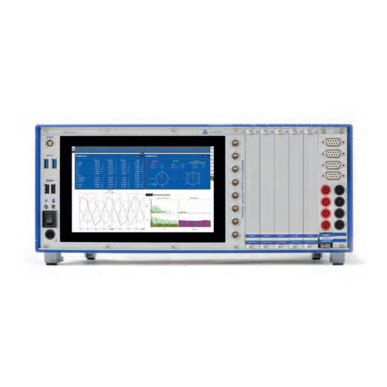
Typical DEWE2-M7 rear view 11 12 13 3 Note: The amount and location of the connectors might vary from system to system and depends on system configuration DEWE2-PA7 • Technical Reference Manual • Printing version 1.0.1 • February 15, 2018... - Page 16 9" multi-touch display The DEWE2-PA7 is equipped with a bright 9" wide screen multi-touch panel (1280 x 800) to control the instrument. Familiar gestures such as pinch and zoom are fully implemented within the operating system and will be described in 'Operating with the touchscreen'.
- Page 17 MAIN SYSTEM Up- / Downstream interface PCIe x1 The DEWE2-PA7 is equipped with a PCI express x1 interface by default. In combination with the TRION™-SYNC-BUS (19) it allows easy high-speed channel expansion with F-series chassis. Note: The PCIe 1X interface connector to connect a DEWE2-F series, is no longer scope of supply for newer models of the DEWE2-PA7.
-
Page 18: Configuration Examples With Trion-1820-Power Module
TRION-1820-POWER module. Standard 4-phase power analyzer with direct input This is the standard configuration of a DEWE2-PA7 for 4-phase (1x 3-phase AC and 1x 1-phase DC) applications. 1 x DEWE2-PA7... - Page 19 TRION-TIMING module GPS sync 1 x DEWE2-PA7 1 x TRION-1820-POWER-4 1 x TRION-BASE for IRIG-B timing source or 1 x TRION-TIMING for IRIG-B, GPS or PPS timing source DEWE2-PA7 • Technical Reference Manual • Printing version 1.0.1 • February 15, 2018...
-
Page 20: Application Examples
MAIN SYSTEM Application examples The TRION-SYNC-BUS (SYNC I/O, SYNC OUT) is used to synchronize two or more DEWE2 systems with up to 100 m distance between each node. The TRION-SYNC-BUS consists of two RJ-45 sockets. One socket being a synchronization OUT, whilst the other one could either be used as synchronization IN or OUT. -
Page 21: Installing A Trion™ Module Into The Dewe2-Pa7
Step 1: Proper ESD precautions must be taken to avoid any damage to the unit. Step 2: Power off and unplug all connected cables including sensors from the DEWE2-PA7 and TRION™ series modules. Step 3: Identify a supported TRION™ peripheral slot. Some modules require a TRION™ STAR-slot. -
Page 22: Touchscreen Gestures
Operating with the Touchscreen Touchscreen gestures The DEWE2-PA7 is equipped with a bright 9" high resolution multi-touch panel to control the DEWE2-PA7. You can use your fingers on the touchscreen, like you would on a smartphone. For example, drag the sidebar from the right side across the screen to open the channel setup. -
Page 23: Trion-1820-Power-4
Continuous maximum allowable input 3 A Input resistance 50 mΩ continued on next page ... DEWE2-PA7 • Technical Reference Manual • Printing version 1.0.1 • February 15, 2018 TRION™ series modules • Technical Reference Manual • Printi ng version 1.2.5 • February 12, 2017... -
Page 24: Signal Connection
MAIN SYSTEM TRION-1820-POWER-4 continued from previous page ... 0.2 A module TRION-POWER-SUB-CUR-02A-1B Range 0.2 A (±0.4 A peak Accuracy DC: ±0.05 % of reading ±0.05 % of range 45 Hz to 1 kHz: ±0.02 % of reading ±0.01 % of range 1 kHz to 10 kHz: ±0.1 % of reading ±0.05 % of range 10 kHz to 50 kHz:... -
Page 25: Exchanging Current Modules
Loosen the torx screw (M2x4, TX6) which secures the sub- module of the channel you want to replace. DEWE2-PA7 • Technical Reference Manual • Printing version 1.0.1 • February 15, 2018 TRION™ series modules • Technical Reference Manual • Printi ng version 1.2.5 • February 12, 2017... - Page 26 MAIN SYSTEM TRION-1820-POWER-4 Secure the replaced sub-module with the torx screw (M2x4, Replace the sub-module. TX6). Max. torque: 0.2 Nm Insert the TRION-1820-POWER-4 module into the housing until Pull up the injector/ejector handle to latch the module. Tighten a resistance appears. the screws at the top and bottom of the TRION-1820-POWER-4 module front panel (4x) to secure the module.
-
Page 27: Block Diagram
Alternatively, this connector can also be used to measure any auxiliary ±10 V signal (e.g. such as windspeed or water fl ow) DEWE2-PA7 • Technical Reference Manual • Printing version 1.0.1 • February 15, 2018 TRION™ series modules • Technical Reference Manual • Printi ng version 1.2.5 • February 12, 2017... -
Page 28: Connection Examples
MAIN SYSTEM TRION-1820-POWER-4 Connection examples Three phase (3P3W) without neutral line Group selection in OXYGEN Power: Three phase (3P3W) without neutral line, using current output transducers Group selection in OXYGEN Power:... - Page 29 Three phase (3P4W) with neutral line Group selection in OXYGEN Power: DEWE2-PA7 • Technical Reference Manual • Printing version 1.0.1 • February 15, 2018 TRION™ series modules • Technical Reference Manual • Printi ng version 1.2.5 • February 12, 2017...
- Page 30 MAIN SYSTEM One phase (1P2W) Group selection in OXYGEN Power: Three phase and one phase (3P3W and 1P2W) Group selection in OXYGEN Power:...
-
Page 31: Main System
Acceleration 30 g, duration 11 ms, pulse form half sine, 3 pumps/direction, 6 directions Class 2M2 (spectral acceleration density 1 m²/s³, frequency range 10 Hz-200 Hz, duration 30 min/ Random vibration (EN 60721-3-2) direction) Tested with SSD DEWE2-PA7 • Technical Reference Manual • Printing version 1.0.1 • February 15, 2018... -
Page 32: Power Supply
MAIN SYSTEM Power supply Standard AC power supply BEA-640 400 W AC power supply Input: ); active PFC Rated input voltage: 100 to 240 V (max. 90 to 264 V Input frequency: 47 to 63 Hz Max. input current: 7 A (115 V ), 3.5 A (230 V Output: Output power:... -
Page 33: Sensor Power Supply
(see user manual). NOTE: The maximum cable lenght from the transducer to the device is 5 m. Longer cable lenghts may cause a too high voltage drop. DEWE2-PA7 • Technical Reference Manual • Printing version 1.0.1 • February 15, 2018... -
Page 34: Maintenance
Maintenance WARNING: The DEWE2-PA7 must not be opened or disassembled except for cleaning the filter pad! The filter pad has to be checked regularly depending on environmental condition! Remove all 8 TX6 screws at the bottom panel and take out the louver with the filter pad. -
Page 35: Cooling Considerations
MAIN SYSTEM Cooling considerations The intake vent of the DEWE2-PA7 is on the bottom of the chassis, where the cooling exhaust vent for the DEWE2-PA7 is on the rear of the chassis. CAUTION: Adequate clearance between the chassis and surrounding equipment or blockages must... -
Page 36: Dimensions
MAIN SYSTEM Dimensions 440,8 * Dimensions in mm (1 inch = 25.4 mm) -
Page 37: Ce-Certificate Of Conformity
EN 61000-6-4 EN 55011 Class B Immunity EN 61000-6-2 Group standard Graz, September 18, 2017 Ing. Thomas Propst / Manager Total Quality Place / Date of the CE-marking DEWE2-PA7 • Technical Reference Manual • Printing version 1.0.1 • February 15, 2018... - Page 38 NOTES...
Need help?
Do you have a question about the DEWE2-PA7 and is the answer not in the manual?
Questions and answers