Table of Contents
Advertisement
Quick Links
Advertisement
Table of Contents

Related Manuals for Dewetron DEWE-VGPS-200C


Summary of Contents for Dewetron DEWE-VGPS-200C
- Page 1 A u t o m o t i v e E n e r g y & P o w e r A n a l y s i s A e r o s p a c e & D e f e n s e T r a n s p o r t a t i o n G e n e r a l T e s t &...
- Page 2 Copyright © DEWETRON elektronische Messgeraete Ges.m.b.H. This document contains information which is protected by copyright. All rights are reserved. Reproduction, adaptation, or translation without prior written permission is prohibited, except as allowed under the copyright laws. All trademarks and registered trademarks are acknowledged to be the property of their owners.
-
Page 3: Table Of Contents
Connecting the DEWE-VGPS-200C hardware to the DAQ-System ………………… 26 Configuration of DEWESoft for the DEWE-VGPS-200C ……………………………… 27 Measurement setup ……………………………………………………………………… 35 CAN BUS …………………………………………………………………………………… 37 EC-Certificate of conformity DE-M060901E • DEWE-VGPS-200C • Technical Reference Manual • Printing version 1.1.4 • November 11, 2008... -
Page 4: Technical Reference
Technical Reference... -
Page 5: General Information, Safety Instructions
Warranty Information A copy of the specific warranty terms applicable to your DEWETRON product and replacement parts can be obtained from your local sales and service office. Support For any support please contact your local distributor first or DEWETRON directly. -
Page 6: Safety Symbols In The Manual
Failure to comply with these precautions or with specific warnings elsewhere in this manual violates safety standards of design, manufacture, and intended use of the product. DEWETRON Elektronische Messgeraete Ges.m.b.H. assumes no liability for the customer’s failure to comply with these requirements. -
Page 7: Safety Instructions For All Dewetron Systems
DO NOT substitute parts or modify equipment: Because of the danger of introducing additional hazards, do not install substitute parts or perform any unauthorized modification to the product. Return the product to a DEWETRON sales and service office for service and repair to ensure that safety features are maintained. -
Page 8: Environmental Considerations
This symbol indicates that this system complies with the European Union’s requirements according to Directive 2002/96/EC on waste electrical and electronic equipment (WEEE). Please find further informations about recycling on the DEWETRON web site www.dewetron.com Restriction of Hazardous Substances This product has been classified as Monitoring and Control equipment, and is outside the scope of the 2002/95/EC RoHS Directive. -
Page 9: Dewe-Vgps-200C
MIL-STD 810F 516.5 procedure I • 3 m autonomous operation non operating test procedure ½ sinus 11 ms 10 g, 3 shocks positive, 3 shocks negative DE-M060901E • DEWE-VGPS-200C • Technical Reference Manual • Printing version 1.1.4 • November 11, 2008... -
Page 10: Device Overview
DEWE-VGPS-200C Device overview With the DEWE-VGPS-200C DEWETRON offers a unique combination of a high dynamic GPS based speed sensor and a GPS synchronized time base generator. This combination allows completely synchronized data acquisition of multiple systems located inside and outside of moving vehicles. -
Page 11: Functionality Of The Leds
Before going to test in a shady environment with tall objects or near to trees, allow the VGPS to settle in an open space for 5 to 10 minutes. DE-M060901E • DEWE-VGPS-200C • Technical Reference Manual • Printing version 1.1.4 • November 11, 2008... -
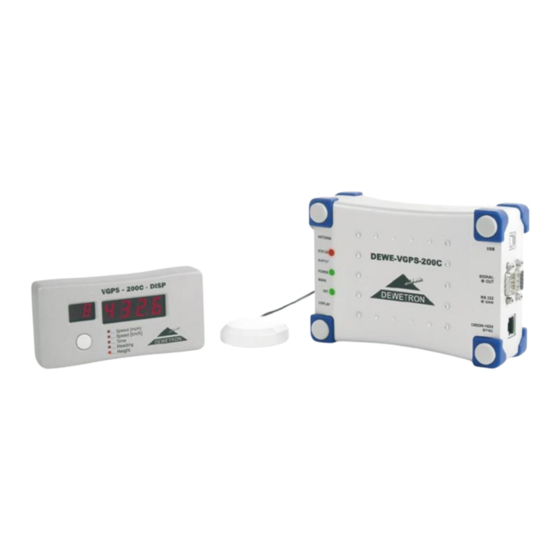
Page 12: Scope Of Supply
DEWE-VGPS-200C Scope of supply GPS aerial RS-232 interface connector interface connector interface connector Power supply connector for cigarette lighter DEWE-VGPS-200C Two BNC output connectors VGPS-Display SYNC output connector for speed and distance Connection Connector overview: Aerial Signal out DC power supply connector... - Page 13 Connects the DEWE-VGPS-200C system to an external DC power supply. Pin assignment 1: +9 to 36 V power supply 2: GND power supply 2-pin Lemo Schematic connector (male) EGJ.1B.302.CLA DE-M060901E • DEWE-VGPS-200C • Technical Reference Manual • Printing version 1.1.4 • November 11, 2008...
- Page 14 DEWE-VGPS-200C Cable for external power supply Type of cable: LIYY 2x0.75, length: 2 m VGPS VGPS-CBL-POW-CL-20 (standard) + Power supply GND power supply VGPS VGPS-CBL-POW-B-20 (optional) + Power supply black GND power supply VGPS DEWE-xxxx VGPS-CBL-POW-S-20 Front view (optional) + Power supply...
- Page 15 Front view 1 2 3 4 5 5 4 3 2 1 6 7 8 9 9 8 7 6 9-pin DSUB male 9-pin DSUB female DE-M060901E • DEWE-VGPS-200C • Technical Reference Manual • Printing version 1.1.4 • November 11, 2008...
- Page 16 DEWE-VGPS-200C Output cable velocity and distance Type of cable: RG-174, length: 2 m VGPS-CBL-OUT-D9-2.0 housing housing / AGND shield VGPS Velocity AGND Velocity Velocity Distance DGND Distance Distance housing / DGND shield Front view 5 4 3 2 1 9 8 7 6...
- Page 17 ANALOG SPEED VELOCITY Front view Front view 5 4 3 2 1 9 8 7 6 shield 9-pin DSUB female 37-pin DSUB male BNC male DE-M060901E • DEWE-VGPS-200C • Technical Reference Manual • Printing version 1.1.4 • November 11, 2008...
-
Page 18: Digital Display Operation
DEWE-VGPS-200C Digital display operation The LED display is used to monitor various GPS parameters. Display description: Blinking middle dashes on all digits - the display is unable to communicate with the VGPS. Pressing and releasing the push-button on the front of the VGPS-Display switches the display to different mode. After pressing the push-button, the LED beside mode changed to appropriate display mode. -
Page 19: Options
This switch can be connected directly to an input of the data acquisition system or to the DEWE-VGPS-200C. The DEWE-VGPS-200C will recognize the exact time of the switching point. A serial command with this time information will be transmitted to the data acquisition unit. DEWESoft displays this event as a separate channel. -
Page 20: Installation Of The Dewesoft Measurement Software
DEWE-VGPS-200C Installation of the DEWESoft measurement software Start the installation software on the System-DVD, shipped with the system. Follow the instructions of the install program according to your license. - Page 21 You can start the software in the Windows start menu or use the icon created on your desktop. For more information about the DEWESoft installation please refer to the DEWESoft Software Users Manual. DE-M060901E • DEWE-VGPS-200C • Technical Reference Manual • Printing version 1.1.4 • November 11, 2008...
-
Page 22: Installation Of The Dewe-Vgps-200C Drivers
DEWE-VGPS-200C Installation of the DEWE-VGPS-200C drivers Execute the file „TI3410Inst.exe“ from the System-DVD (usually D:\Install\Drivers\7_Communication\DEWE-USB where D is the units DVD-Drive letter). Click on “Continue Anyway” to accept the software installation. - Page 23 Power the DEWE-VGPS-200C and connect it to the DAQ-System via USB. When the hardware screen appears, select “No, not this time” Select “Install from a list or a specific location” DE-M060901E • DEWE-VGPS-200C • Technical Reference Manual • Printing version 1.1.4 • November 11, 2008...
- Page 24 DEWE-VGPS-200C Choose the DEWE-USB folder from the DEWE-System DVD (D:\Install\Drivers\7_Communication\DEWE-USB) When prompted for the driver installation, select “Continue Anyway”...
- Page 25 Please note the COM port listed next to the “USB-Serial port” entry. This COM port is used for communicating with the DEWE-VGPS-200C when connected via USB. The driver has been successfully installed. DE-M060901E • DEWE-VGPS-200C • Technical Reference Manual • Printing version 1.1.4 • November 11, 2008...
-
Page 26: Connecting The Dewe-Vgps-200C Hardware To The Daq-System
Sync-cable Synchronization to DEWE-ORION-1624 One of the unique features of the DEWE-VGPS-200C is the possibility to synchronize also data acquisition systems using delta sigma ADC technology like DEWE-ORION-1624. The main challenge is to produce the up to 256 times over sample clock used for these types of analog to digital converters. For this purpose the DEWE- VGPS-200C is equipped with a RJ45 connector for connection to the DEWETRON data acquisition system. -
Page 27: Configuration Of Dewesoft For The Dewe-Vgps-200C
(System Hardware Setup GPS): Select V-GPS from the GPS device dropdown menu. DEWESoft will automatically try to find a GPS on the standard COM port. DE-M060901E • DEWE-VGPS-200C • Technical Reference Manual • Printing version 1.1.4 • November 11, 2008... - Page 28 If the GPS can not be found select the port where the GPS is connected from the COM port dropdown menu and hit the Refresh button.If the DEWE-VGPS-200C is connected to the DAQ-System via RS232 interface, select the onboard COM port (usually COM1 or COM2). If it is not connected via USB interface, select the COM port which is listed next to the entry "USB Serial port"...
- Page 29 Receiver dynamic settings Depending on the application, the DEWE-VGPS-200C offers the possibility to set it into three different settings. These can be done in the pull down menu Receiver dynamic settings. Highest (car performance for analog out): This setting should be used if the low latency time of 12 ms at the analog and speed output is needed.
- Page 30 DEWE-VGPS-200C The most accurate operation is the differential mode using a additional Local Base Station. For that operation two VGPS systems are required: One VGPS system is fixed mounted (at a Local Base Station) the second is for mobile operation. The fixed VGPS sends the correction data (for example via GSM-modem) to the mobile VGPS.
- Page 31 Timing settings Hardware setup In addition to a high precision speed sensor the DEWE-VGPS-200C is also a high precision timing source for synchronized data acquisition. In this operation mode the DEWE-VGPS-200C generates the clock for the data acquisition system. Beside of generating a clock from of up to 10 MHz for data acquisition systems a clock engine for synchronized acquisition using DEWE-ORION-1624 is included also.
- Page 32 The maximum allowed correction limit is 500 ms. The graph below gives an idea how the DEWE-VGPS-200C behaves when the GPS signal is lost during data acquisition. In this example the drift of the oscillator is smaller than the allowed correction limit.
- Page 33 PC time. The actual time form the DEWE-VGPS-200C is shown at the right top corner. In addition to this an indicator gives you the information if the clock generator is locked to the GPS data (green dot) or if it is operating in FREE-RUN mode (red dot).
- Page 34 DEWE-VGPS-200C As default the local time is stored inside the data file. But if the measurement results from multiple systems located in different time zones should be analyzed it is recommended to set to UTC or GPS time. Doing so, the...
-
Page 35: Measurement Setup
When you finished the hardware settings, click on the “Setup” button. Channel Setup The screenshot below shows the channel setup screen of the DEWE-VGPS-200C. In the column ON/OFF you can select the channels for storing during the measurement. The default channel names are displayed in the column NAME. - Page 36 DEWE-VGPS-200C Measurement Now you are ready for measurement. Clicking the “GPS“ button opens the measurement screen. With the “Store“ and “Stop“ button you can control the measurement manually. Analyze After measurement you can analyze and protocol the stored data. One click on the “Analyze“ button gives you the possibility to choose a recorded data file and analyze it.
-
Page 37: Can Bus
DEWE-VGPS-200C CAN BUS Beside the RS-232 and USB interface the DEWE-VGPS-200C can be also operated with a CAN high speed interface with 500 kBaud. A required DBC-file is available for automatic settings of the data acquisition system. The update rate of the GPS signals is 20 times per second on the CAN bus. In addition to the standard GPS channels the PPS channel is available also. - Page 38 DEWE-VGPS-200C The picture below shows you how to eliminate the latency time already during the data acquisition. Inside the CAN at each CAN identifier the latency can be defined for automatic correction. The typical delay on the CAN interface is around 18 ms.
- Page 39 If the number of received satellites is lower than the limit the velocity is set to 500 km/h. Please refer also to the Hardware setup 16) Channel name Heading: The direction (true track over ground) is measured with a resolution of 0.01°. DE-M060901E • DEWE-VGPS-200C • Technical Reference Manual • Printing version 1.1.4 • November 11, 2008...
- Page 40 DEWE-VGPS-200C Identifier name Mark (base +5: 0x131): The exact time of the mark input is measured with an accuracy of better than 1 µs. The exact time of this event is transferred. 17) Channel name Mark_s: These are the seconds since midnight UTC when the event occurs.
-
Page 41: Ec-Certificate Of Conformity
EN 55011 Class B Immunity EN 61000-6-2 Group standard Graz, October 14, 2008 Dipl.-Ing. Roland Jeutter / Managing director Place / Date of the CE-marking DE-M060901E • DEWE-VGPS-200C • Technical Reference Manual • Printing version 1.1.4 • November 11, 2008... - Page 42 Notes...
Need help?
Do you have a question about the DEWE-VGPS-200C and is the answer not in the manual?
Questions and answers