Advertisement
Quick Links
Advertisement

Related Manuals for ADJ UB 12H


Summary of Contents for ADJ UB 12H
- Page 1 UB 12H User Manual...
- Page 2 ©2023 ADJ Products, LLC all rights reserved. Information, specifications, diagrams, images, and instructions herein are subject to change without notice. ADJ Products, LLC logo and identifying product names and numbers herein are trademarks of ADJ Products, LLC. Copyright protection claimed includes all forms and matters of copyrightable materials and information now allowed by statutory or judicial law or hereinafter granted.
-
Page 3: Table Of Contents
C O N T E N T S Introduction Features | Installation | Warranty Registration Limited Warranty Safety Precautions DMX Set Up Operating Instructions Primary-Secondary Configuration | Multiple Unit Power Linking UC IR Control DMX Traits Section Mode | Dimming Curves Color Macro Chart Magnetic Quick Align Fuse Replacement | Trouble Shooting | Cleaning... -
Page 4: Introduction
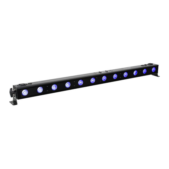
Please do not return this unit to your dealer without contacting customer support first. Introduction: The UB 12H is a DMX intelligent, LED bar fixture. This fixture can be used in a stand alone mode or connected in a primary/secondary configuration. This fixture has six operating modes: Static Color mode, RGBWA+UV Dimmer mode, Program mode, Auto mode, Sound Active mode, and DMX control mode. - Page 5 WA R R A N T Y R E G I S T R AT I O N The UB 12H carries a 2 year limited warranty. Please fill out the enclosed warranty card to validate your purchase. All returned service items, whether under warranty or not, must be freight pre-paid and accompanied by a return authorization (R.A.) number.
-
Page 6: Limited Warranty
ADJ Products, LLC be liable for any loss or damage, direct or consequential, arising out of the use of, or inability to use, this product. -
Page 7: Safety Precautions
S A F E T Y P R E C A U T I O N S • To reduce the risk of electrical shock or fire, do not expose this unit rain or moisture . • Do not spill water or other liquids into or on to your unit. •... - Page 8 S A F E T Y P R E C A U T I O N S RISK GROUP 3 - RISK OF EXPOSURE TO ULTRAVIOLET (UV) RADIATION! FIXTURE EMITS HIGH INTENSITY ULTRAVIOLET (UV) LIGHT AT A WAVELENGTH OF 390NM - 410NM.
-
Page 9: Dmx Set Up
D M X S E T U P Power Supply: This unit contains an automatic volt a ge switch, which will automatically sense the voltage when it is plugged into the power source. With this switch, there is no need to worry about the correct power voltage, and this unit can be plugged in almost anywhere. ... - Page 10 2 and 3 of a male XLR connector (DATA + and DATA -). This unit is inserted in the female XLR connector of the last unit in your daisy chain to terminate the line. Using a cable terminator (ADJ part number Z-DMX/T) will decrease the possibilities of erratic behavior. Termination reduces signal errors and avoids signal transmission problems and interference.
-
Page 11: Operating Instructions
O P E R AT I N G I N S T R U C T I O N S LED Display On/Off: To set the LED display to turn off after 10 seconds of inactivity, press the MODE button until “don” is displayed, then press the UP button to toggle the display to “doff”. - Page 12 O P E R AT I N G I N S T R U C T I O N S Auto Run Mode: In this mode, the unit will run an auto program. 1. Plug the fixture in and press the MODE button until “AUTO” is displayed. 2.
- Page 13 ADJ Remote Activation: This function is used to activate and deactivate the IR sensor. When this function is activated, you can control the fixture using the ADJ UC IR. Please see the UC IR Remote section of this manual for detailed information.
- Page 14 O P E R AT I N G I N S T R U C T I O N S Dimmer Curve: This setting is used to set the dimming curve used with DMX mode. See the Dimming Curves section of this manual for detailed information.
- Page 15 P R I M A R Y- S E C O N D A R Y C O N F I G U R AT I O N This function allows units to be linked together to run in a Primary-Secondary set up, in which one unit will act as the controlling unit and the others will react to the controlling unit’s built-in programs.
-
Page 16: Uc Ir Control
The UC IR infrared remote gives the user control of various functions, as listed below. To control the fixture, the remote must be aimed at the front of the fixture. Maximum range is 30 feet. To use the ADJ UC IR, the fixture’s infrared sensor must first be activated, as described in the Operating Instructions section of this manual. - Page 17 D M X T R A I T S CHANNEL FUNCTION VALUES 10Ch 12Ch 36Ch 000 - 255 Red, 0% to 100% 000 - 255 Green, 0% to 100% 000 - 255 Blue, 0% to 100% 000 - 255 White, 0% to 100% 000 - 255 Amber, 0% to 100% 000 - 255 UV, 0% to 100% Color Macros, see Color Macro Chart section of...
-
Page 18: Dmx Traits
D M X T R A I T S CHANNEL FUNCTION VALUES 10Ch 12Ch 36Ch Strobing 000 - 031 LED Off 032 - 063 LED On 064 - 095 Strobing, slow to fast 096 - 127 LED On 128 - 159 Pulse Strobing, slow to fast 160 - 191 LED On 192 - 223 Random Strobing, slow to fast 224 - 255 LED On... - Page 19 D M X T R A I T S CHANEL VALUES FUNCTION 10Ch 12Ch 36Ch 000 - 255 Blue 4, 0% to 100% 000 - 255 White 4, 0% to 100% 000 - 255 Amber 4, 0% to 100% 000 - 255 UV 4, 0% to 100% 000 - 255 Red 5, 0% to 100% 000 - 255 Green 5, 0% to 100% 000 - 255 Blue 5, 0% to 100%...
- Page 20 S E C T I O N M O D E Section 1 Section 2 Section 3 Section 4 Section 5 Section 6 D I M M I N G C U R V E S DIMMER 100% Time (ms) 0 Sec Rise Time Down Time...
- Page 21 C O L O R M A C R O C H A R T COLOR MACRO COLOR MACRO VALUES VALUES 000 - 003 128 - 131 G+B+W 004 - 007 132 - 135 G+B+A 008 - 011 Green 136 - 139 G+B+UV 012 - 015 Blue...
- Page 22 M A G N E T I C Q U I C K A L I G N This unit features a magnetic quick align feature which allows multiple fixtures to be connected se- curely end-to-end. This feature is to be used exclusively when the fixtures are positioned on a flat surface such as a floor or stage for uplighting.
- Page 23 F U S E R E P L A C E M E N T Disconnect the unit from its power source, then remove the power cord from the unit. Use a flat head head screwdriver to remove the fuse holder. Remove the fuse located inside the fuse holder and replace it with the new fuse of the same rating.
- Page 24 Long Life LEDs (Rated at approximately 50,000 hrs.) • Power Draw: 88W @ 120V. • Linkable: DMX via 3-pin XLR cable; Power via IEC. Daisy-chain power (Up to 7 UB 12H fixtures max., @ 120V can be power linked) • With Wired Digital Communication Network •...
- Page 25 D I M E N S I O N A L D R AW I N G S 1.91”/74mm 3.57”/90.78mm 2.67”/68mm 2.36”/60mm 2.55”/65mm 1.91”/74mm 3.57”/90.78mm...
Need help?
Do you have a question about the UB 12H and is the answer not in the manual?
Questions and answers