
Subscribe to Our Youtube Channel
Related Manuals for REMKO LTE 120


Summary of Contents for REMKO LTE 120
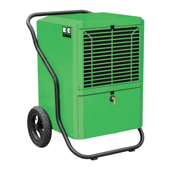
- Page 1 Assembly and operating instructions REMKO LTE 120 Dehumidifier Read the instructions prior to performing any task! 0178-2018-01 Edition 1, en_GB...
- Page 2 Read these operating instructions carefully before commis- sioning / using this device! These instructions are an integral part of the system and must always be kept near or on the device. Subject to modifications; No liability accepted for errors or mis- prints! Installation and operating instructions (translation of the orig- inal)
-
Page 3: Table Of Contents
Table of contents Safety and usage instructions......................4 1.1 General safety notes........................4 1.2 Identification of notes........................4 1.3 Personnel qualifications........................4 1.4 Dangers of failure to observe the safety notes................4 1.5 Safety-conscious working....................... 4 1.6 Safety instructions for the operator....................5 1.7 Safety notes for installation, maintenance and inspection work............ -
Page 4: Safety And Usage Instructions
REMKO LTE Safety and usage instructions CAUTION! This combination of symbol and signal word 1.1 General safety notes warns of a potentially hazardous situation, which if not avoided may cause injury or mate- Carefully read the operating manual before com- rial and environmental damage. -
Page 5: Safety Instructions For The Operator
1.6 Safety instructions for the operator NOTICE! The operational safety of the units and compo- Extensions to the connection cable must only nents is only assured providing they are used as be conducted by authorised specialist electri- intended and in a fully assembled state. cians, taking into consideration the unit power consumption, cable length and local use. -
Page 6: Unauthorised Modification And Changes
"certificate of warranty" to safe manner, e.g. using certified firms and recy- REMKO GmbH & Co. KG at the time when the cling specialists or at collection points. units are purchased and commissioned. -
Page 7: Technical Data
Technical data 2.1 Unit data Unit type LTE 120 Operating range, temperature °C 3 to 32 Operating range, humidity % RH 40 to 100 Dehumidification capacity max. l/day At 30 °C/80 % RH 102.4 l/day (DER) At 20 °C/70 % RH l/day (DER) 62.5... - Page 8 REMKO LTE Unit type LTE 120 Dimensions Depth Width Height Height incl. transportation bracket Weight 70.0 EDP no. 618900 EDP no. Unit with condensate pump 618905 (DER) = Dehumidification output figure in accordance with DIN EN 810 Contains greenhouse gas according to Kyoto protocol Noise level measurement DIN 3744 - KL 2 Max.
-
Page 9: Design And Function
The use of REMKO air dehumidifiers With regard to energy consumption, air dehumidifi- Even if windows and doors are well insulated, cation has one distinct advantage: water and moisture are still capable of pene- trating thick concrete walls. - Page 10 Evaporation occurs on the surface = Transfer 10.4 of water vapour to the ambient air The air containing water vapour is constantly 13.8 circulated through the REMKO air dehumidifier. 12.9 18.2 The air is dehumidified and, slightly heated, leaves the unit in order to re-absorb water...
- Page 11 Functional principle of the air dehumidifier As it flows through or over the evaporator, the air stream is cooled to dew point. The water vapour con- denses, and is collected in a condensate trap from where it is drained off. Fig.
-
Page 12: Unit Description
REMKO LTE Energy must be supplied when liquid is converted The units may be used for the drying and dehumid- into a gas. This energy is designated as evapora- ification of areas such as: tion heat. It does not cause any increase in tem-... - Page 13 Fig. 5: Air dehumidification operating principle A: Dehumidified room air 2: Condenser B: Moist room air 3: Evaporator 1: Fan 4: Compressor...
-
Page 14: Assembly
REMKO LTE Assembly 4.1 Setting up the unit NOTES: For the best economic and safe use of the units, – Keep windows and doors closed! the following notes must be followed in full: – Keep at least 0.5 m away from walls. -
Page 15: Electrical Wiring
Electrical wiring 5.1 General notes Extensions to the connection cable may only be carried out by authorised electricians, sub- The units are operated with 230 V / 50 Hz ject to the length of the cable, connected load alternating current of the unit and taking into consideration how The electrical connection is made using a built- the unit is used at its location... -
Page 16: Commissioning
REMKO LTE Commissioning Starting the unit Start the unit as follows: Before commissioning the unit or if local require- ments dictate, the air-inlet grille and air-outlet grille Plug the unit's power plug into a properly must be checked for contamination. - Page 17 Control and display panel: Fig. 8: Control panel If the humidity lies below the target humidity set ON / OFF key: (i.e.: rRH < -3%), the compressor and the fan After actuating the ON / OFF key whilst switched motor stop. If the humidity is higher than the target off, the unit starts as soon as the humidity in the humidity set (i.e.: rRH >...
- Page 18 REMKO LTE Function or situation Segment display Power plug is plugged in, the unit is Current measured room humidity is displayed switched off The unit starts Current measured room humidity is displayed During the adjustment of the target room The target room humidity set is displayed...
- Page 19 If Tc is >50 °C and the compressor runs within 5 RT °C INDICATOR: minutes, the unit switches off and the error code If the "ROOM TEMP" key is pressed, the RT indi- "E3" is shown in the segment display [3] and the cator [10] illuminates for 5 seconds.
- Page 20 REMKO LTE Function table: Power plug Operating status: Unit oper- Functions Defrost function inserted ating or in standby After the Standby 30 min. timer 30 mins. The unit starts expires if (no operation) defrost timer (no operation) r RH >+4 % function has Te<=1 °C...
-
Page 21: Condensate Removal
Condensate removal Depending on the air temperature and the relative humidity, condensed water will drip into the con- densate trap either continuously or only during the defrosting phases and can drain through the hose connection. Unit operation with hose connection Due to its high dehumidification performance, the unit is designed to drain the condensate directly into a suitable collection container via a sloping... - Page 22 REMKO LTE Fig. 12: Drain hose passage through the base plate NOTICE! Unit operation with condensate pump is only possible with units that were shipped with the pump installed. NOTICE! If the condensate pump runs for an extended period of time, the condensate trap and the hoses must be checked for contamination at regular intervals.
-
Page 23: Troubleshooting And Customer Service
Troubleshooting and customer service The unit and components are manufactured using state-of-the-art production methods and tested several times to verify that they function correctly. However, if malfunctions do occur, please check the functions as detailed in the list below. Please inform your dealer if the unit is still not working correctly after all function checks have been performed! Operational malfunctions Malfunction... -
Page 24: Shutdown
REMKO LTE Display of error codes Error codes are displayed in the segment display [1]. Fig. 13: Segment display Error code description: Error code Error description Evaporator temperature probe (Te) defective Condensate temperature probe (Tc) defective Compressor runs within 5 minutes and the condenser temperature (Tc) > 50 °C E3 flashes Compressor runs over 5 minutes and the condenser temperature (Tc) >... -
Page 25: Care And Maintenance
Care and maintenance 10.1 Care and maintenance Cleaning the dust filter General notes NOTICE! Check the inlet and outlet grille and the dust filter for contamination on a regular basis. Regular care and maintenance is fundamental to a long service life and fault-free operation of the unit. - Page 26 REMKO LTE Cleaning the units Clean the evaporator fins, for example with a lukewarm soap solution (or similar). The unit housing must be opened to allow the inside of the unit to be cleaned and to provide access to electrical components.
-
Page 27: Maintenance Protocol
10.2 Maintenance protocol Unit type: Unit number: -------------------------------- --------------------------------------- Unit cleaned - outside - Unit cleaned - inside - Fan blade cleaned Fan housing cleaned Condenser cleaned Evaporator cleaned Fan function checked Air-inlet grid with filter cleaned Unit checked for damage Safety devices checked All fastening screws checked Electrical safety check... -
Page 28: General View Of Unit And Spare Parts
REMKO LTE General view of unit and spare parts 11.1 Exploded view of the unit We reserve the right to modify the dimensions and design as part of the ongoing technical development process. -
Page 29: Spare Parts List
11.2 Spare parts list No. Designation LTE 120 Lock for sealing flap Protective intake grille Dust filter Unit housing Control panel Filter grill, interior Evaporator fin package cpl. NTC evaporator probe NTC condenser probe Top separating panel Reinforcement plate above, left... - Page 30 REMKO LTE No. Designation LTE 120 Humidity / temp. probe Humidity / temp. probe holder Base plate Hub cover cap Wheel screw Wheel Wheel Axle On request by providing the Axle fastening serial number Compressor, cpl. Housing cover Operating condenser...
-
Page 31: Index
Index Air dehumidification, description ... . . 9 Operating sequence ..... 12 Automatic restart after power failure . - Page 32 SFlb Customer Service Our equipment operates precisely and reliably. However, in the event of a fault, REMKO customer service is quickly at the scene. Our comprehensive network of experienced dealers always guarantees quick and REMKO GmbH & Co. KG reliable service.
Need help?
Do you have a question about the LTE 120 and is the answer not in the manual?
Questions and answers