
Related Manuals for Videx VK4K/3656 Series


Summary of Contents for Videx VK4K/3656 Series
- Page 1 English VIDEOKIT VK4K/3656 SERIES “6 Wire” bus one way, two way videokit VK4K VK4KC 3656 Installation handbook We recommend 66250454-EN This equipment is installed by a V 3.4.1 Competent Electrician, Security or 15/09/16 Communications Engineer.
-
Page 2: Table Of Contents
VK4K/3656 Series “6 wire Bus” videokit Index Introduction ....................................2 System components and available versions ..........................3 General directions for installation ..............................5 Troubleshooting guide .................................. 6 Art. 4833 Speaker unit ................................... 7 Art. 4800 - 4800M Digital codelock module ..........................10 4000 Series surface and flush mounting door station installation .................. -
Page 3: System Components And Available Versions
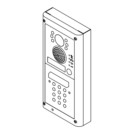
VK4K/3656 Series “6 wire Bus” videokit System components and available versions VK4K/3656 Colour videokit. OUTDOOR INDOOR STATION STATION Videophone 135,0 45,0 22,5 49,8 Art. 3656 pag. 15 Camera unit Art. 4833 pag. 7 ACCESSORIES Power supply 15,7 Art. 850K 43,8 pag. 5 120,0... - Page 4 VK4K/3656 Series “6 wire Bus” videokit System components and available versions VK4KC/3656 Colour videokit plus a codelock module. OUTDOOR INDOOR STATION STATION 135,0 45,0 24,0 51,0 Videophone Art. 3656 pag. 15 Camera unit Art. 4833 pag. 7 ACCESSORIES Power supply Codelock Art. 850K unit pag.
-
Page 5: General Directions For Installation
VK4K/3656 Series “6 wire Bus” videokit General directions for installation CONNECTION TO MAINS The system must be installed according to national rules in force, in particular we recommend to: • Connect the system to the mains through an all-pole circuit breaker which shall have contact separation of at least 3mm in each pole and shall disconnect all poles simultaneously;... -
Page 6: Troubleshooting Guide
VK4K/3656 Series “6 wire Bus” videokit Troubleshooting guide In case of system failure, try the following preliminary checks: • Check that the cables are connected as shown in the installation diagram and that the cables are firmly fixed into the relevant terminals;... - Page 7 VK4K/3656 Series “6 wire Bus” videokit Art. 4833 Speaker unit R02A 1 2 3 4 J1 J2 J3 J4 12Vout DATA Fig. 1 Fig. 2 DESCRIPTION Speaker unit module Art. 4833 comprising of high quality auto iris lens CCD Day/Night colour camera with infrared illumination LEDs.
-
Page 8: Art. 4833 Speaker Unit
VK4K/3656 Series “6 wire Bus” videokit Art. 4833 Speaker unit SETTINGS (DIP-SWITCH & JUMPERS) 4 WAY DIP-SWITCH First two switches are used to set the speaker unit address: the speaker unit address is required for camera recall operation on 2 or more entrance systems. - Page 9 VK4K/3656 Series “6 wire Bus” videokit Art. 4833 Speaker unit BUILT-IN RELAYS – BACK EMF PROTECTION The Art. 4833 includes selectable back EMF protection on the relays. The jumpers marked J4 (One jumper for each relay) are used to select the protection type. When using a fail secure lock with connections C & NO the jumper should be in the NO position. When using a fail open lock with connections C &...
- Page 10 GENERAL DIRECTIONS FOR INSTALLATION In order to achieve the best results from the schematics described it is necessary to install only original VIDEX equipment, strictly keeping to the items indicated on each schematic and follow these General Directions for Installation: •...
-
Page 11: Art. 4800 - 4800M Digital Codelock Module
VK4K/3656 Series “6 wire Bus” videokit Art. 4800M Digital codelock module BUZZER BACK EMF When using intercoms with buzzer call (Art.924/926, SMART1/2, 3101/2, 3001/2 and 3021/2) add one 0.1uF (100nF) capacitor be- tween terminals 3 and 6 on the telephone. BUILT-IN RELAYS – BACK EMF PROTECTION The Art. 4800M includes selectable back EMF protection on the relays. - Page 12 VK4K/3656 Series “6 wire Bus” videokit Art. 4800M Digital codelock module TECHNICAL SPECIFICATION Power Supply: 12/24 Vac/dc – 2VA Power Consumption: Stand-by: 20mA Operating: 70mA Working Temperature: -10 +50° C PROGRAMMING FLOW-CHART ENTER “ENGINEER’S CODE“ First time 6 times 1 "111111"...
- Page 13 VK4K/3656 Series “6 wire Bus” videokit 4000 Series Surface and flush mounting door station installation EXAMPLE: INSTALLING A FOUR MODULE OUTDOOR STATION fig. 1 fig. 2 fig. 3 fig. 4 fig. 5 fig. 6 fig. 7 fig. 8 fig. 9 fig.
-
Page 14: 4000 Series Surface And Flush Mounting Door Station Installation
VK4K/3656 Series “6 wire Bus” videokit 4000 Series Surface and flush mounting door station installation INSTALLING A SURFACE MOUNT DOOR STATION 1. Place the surface box against the wall (165-170cm between the top of the box and the floor level as shown in Fig. 1) and mark the fixing holes for the wall plugs and the hole for the cables E (fig. 2). - Page 15 VK4K/3656 Series “6 wire Bus” videokit Art. 3656 3.5" colour display videophone 1 2 3 6 7 8 Fig. 1 Fig. 2 PUSH BUTTONS Camera recall button. Pick up the handset then press the button (Press once for door/gate 1, twice for 2 and so on up to a maximum of 4 entrances): the relevant LED switches ON and the monitor switches on showing the video coming from the door panel.
-
Page 16: Art. 3656 3.5" Colour Display Videophone
VK4K/3656 Series “6 wire Bus” videokit Art. 3656 3.5" colour display videophone LEDS CONTROLS ON LED. Call tone volume control (3 levels). Switched ON when the videophone is operating. Hue control. Door open LED. Can be used to indicate the status of a door or gate. It requires Brightness control. - Page 17 VK4K/3656 Series “6 wire Bus” videokit 3600 Series Videophone wall mounting instructions Fig. 2 Fig. 1 Fig. 3 Fig. 5 Fig. 4 1. Cables must be fed through the opening E (Fig. 2) of the mounting plate C, which should be fitted approximately 135cm from finished floor level as shown in Fig.
-
Page 18: Installation Diagrams
This manual has been written and revised carefully. The instructions and the descriptions which are included in it are referred to VIDEX parts and are correct at the time of print. However, subsequent VIDEX parts and manuals, can be subject to changes without notice. - Page 19 VK4K/3656 Series “6 wire Bus” videokit Installation diagrams VIDEOKIT VK4K-1/3656, VK4K-1S/3656 VK4K/3656 Series - Installation handbook 66250454-EN - V 3.4.1 - 15/09/16...
- Page 20 VK4K/3656 Series “6 wire Bus” videokit Installation diagrams VIDEOKIT VK4K-2/3656, VK4K-2S/3656 VK4K/3656 Series - Installation handbook 66250454-EN - V 3.4.1 - 15/09/16...
- Page 21 VK4K/3656 Series “6 wire Bus” videokit Installation diagrams VIDEOKIT VK4KC-1/3656, VK4KC-1S/3656 VK4K/3656 Series - Installation handbook 66250454-EN - V 3.4.1 - 15/09/16...
- Page 22 VK4K/3656 Series “6 wire Bus” videokit Installation diagrams VIDEOKIT VK4KC-2/3656, VK4KC-2S/3656 VK4K/3656 Series - Installation handbook 66250454-EN - V 3.4.1 - 15/09/16...
- Page 23 VK4K/3656 Series “6 wire Bus” videokit Installation diagrams VIDEOKIT VK4K-1/3656, VK4K-1S/3656 WITH ADDITIONAL INTERCOM AND EXTENSION SOUNDER VK4K/3656 Series - Installation handbook 66250454-EN - V 3.4.1 - 15/09/16...
- Page 24 VK4K/3656 Series “6 wire Bus” videokit Installation diagrams VIDEOKIT VK4K-1/3656, VK4K-1S/3656 WITH ADDITIONAL DOOR PANEL FOR 2 ENTRANCES SYSTEM VK4K/3656 Series - Installation handbook 66250454-EN - V 3.4.1 - 15/09/16...
- Page 25 VK4K/3656 Series “6 wire Bus” videokit Installation diagrams VIDEOKIT VK4KC-1S/4900/3656, VK4KC-1S/4900/3656 VK4K/3656 Series - Installation handbook 66250454-EN - V 3.4.1 - 15/09/16...
- Page 26 VK4K/3656 Series “6 wire Bus” videokit Installation diagrams VIDEOKIT VK4K-2/3656 - VK4K-2S/3656 WITH ART. 316 21/10/2015 22/10/2015 Marco Rongoni vk4k36h-001.dwg VK4K/3656 Series - Installation handbook 66250454-EN - V 3.4.1 - 15/09/16...
- Page 27 VK4K/3656 Series “6 wire Bus” videokit Installation diagrams TWO ENTRANCES SYSTEM INSTALLATION 18Vdc ART. 323/18 230V Push to exit Push to exit Title: Data creazione: Foglio 29/10/2015 Titolo: Data modifica: 29/10/2015 Videx Electronics S.p.A. Notes: Autore: Marco Rongoni Via del Lavoro 1, 63846 Monte Giberto (FM) Note: Cod.File:...
- Page 28 MANUFACTURER CUSTOMER SUPPORT VIDEX ELECTRONICS S.P.A. All Countries: VIDEX ELECTRONICS S.P.A. Via del Lavoro, 1 - 63846 Monte Giberto (FM) Italy www.videx.it - technical@videx.it Tel (+39) 0734 631669 - Fax (+39) 0734 632475 Tel: +39 0734-631669 - Fax: +39 0734-632475 www.videx.it - info@videx.it...
Need help?
Do you have a question about the VK4K/3656 Series and is the answer not in the manual?
Questions and answers