Videx 6256 Series Installation Handbook
“6 wire” bus one way, two way videokit
Hide thumbs
Also See for 6256 Series:
- Installation handbook (36 pages) ,
- Manual (16 pages) ,
- Quick manual (2 pages)
Table of Contents
Advertisement
Quick Links
Advertisement
Table of Contents

Related Manuals for Videx 6256 Series


Summary of Contents for Videx 6256 Series
- Page 1 VIDEOKIT Rev.0.1 VK8K/6256 SERIES “6 Wire” bus one way, two way videokit VK8K VK8KC 6256 Installation handbook We recommend 66250865-EN - V4.0 - 15/03/19 This equipment is installed by a Competent Electrician, Security or Communications Engineer.
-
Page 2: Table Of Contents
This manual has been written and revised carefully. The instructions and the descriptions which are included in it are referred to VIDEX parts and are correct at the time of print. However, subsequent VIDEX parts and manuals, can be subject to changes without notice. -
Page 3: System Components And Available Versions
VK8K/6256 Series “6 wire Bus” videokit System components and available versions VK8K/6256 Colour videokit. OUTDOOR INDOOR STATION STATION Videophone Art. 6256 pag. 14 Camera unit Art. 8833 pag. 7 ACCESSORIES Power supply Art. 850K pag. 5 Video distributor Art. 316N pag. 17 Flush Surface... - Page 4 VK8K/6256 Series “6 wire Bus” videokit System components and available versions VK8KC/6256 Colour videokit plus a codelock module. OUTDOOR INDOOR STATION STATION Videophone Art. 6256 pag. 14 Camera unit Art. 8833 pag. 7 ACCESSORIES Codelock Power supply module Art. 850K Art. 8800 pag. 5 pag.
-
Page 5: General Directions For Installation
VK8K/6256 Series “6 wire Bus” videokit General directions for installation CONNECTION TO MAINS The system must be installed according to national rules in force, in particular we recommend to: • Connect the system to the mains through an all-pole circuit breaker which shall have contact separation of at least 3mm in each pole and shall disconnect all poles simultaneously;... -
Page 6: Troubleshooting Guide
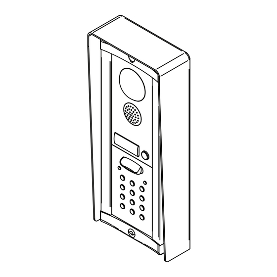
VK8K/6256 Series “6 wire Bus” videokit Troubleshooting guide In case of system failure, try the following preliminary checks: • Check that the cables are connected as shown in the installation diagram and that the cables are firmly fixed into the relevant terminals;... - Page 7 VK8K/6256 Series “6 wire Bus” videokit Art. 8833 Speaker unit Rev.0.1 When installing you see the back side of the door panel. 8833-1 Colour Aluminium 8833-2 B&W Stainless steel Fig. 1 Front Fig. 2 Back (upside down view) CONTROLS (SPEAKER & MICROPHONE VOLUME) Trimmer to adjust the speaker volume.
-
Page 8: Art. 8833 Speaker Unit
VK8K/6256 Series “6 wire Bus” videokit Art. 8833 Speaker unit HOW TO CONNECT ELECTRIC LOCK The “door-open” relay can operate either as “dry contact” or “capacitive discharge” mode. • In “dry contact” operation mode the relay works in a traditional way, a power supply or a power source is needed to operate the lock (12-24Vac/dc 2A max), and activation lasts according to the door opening time programmed. - Page 9 GENERAL DIRECTIONS FOR INSTALLATION In order to achieve the best results from the schematics described it is necessary to install only original VIDEX equipment, strictly keeping to the items indicated on each schematic and follow these General Directions for Installation: •...
-
Page 10: Art. 8800 - Art. 8800-3 Digital Codelock Module
VK8K/6256 Series “6 wire Bus” videokit Art. 8800 - Art. 8800-3 Digital codelock module PROGRAMMING • Enter ENGINEER’S CODE: first time type six times 1 (111111 First time six times ENTER THE factory preset) and press ENTER (The red LED will illuminate). - Page 11 VK8K/6256 Series “6 wire Bus” videokit Art. 8800 - Art. 8800-3 Digital codelock module RE-PROGRMMING GUIDE Engineer’s code ENTER THE ENGINEER’S CODE Press Enter Relay 1 code (Red light will illu- Relay 2 code minate*) Alternatively enter a RE-ENTER THE new engineer’s code ENGINEER’S CODE...
- Page 12 VK8K/6256 Series “6 wire Bus” videokit 8000 Series Surface and flush mounting door station installation EXAMPLE: INSTALLING A TWO MODULE OUTDOOR STATION Fig. 1 Fig. 2 Fig. 3 Fig. 4 Fig. 5 Fig. 6 Fig. 7 Fig. 8 Fig. 9 Fig.
-
Page 13: 8000 Series Surface And Flush Mounting Door Station Installation
VK8K/6256 Series “6 wire Bus” videokit 8000 Series Surface and flush mounting door station installation INSTALLING A FLUSH MOUNTING DOOR STATION 1. Mount back box (Fig. 2) at 165 cm from ground level (Fig. 1); 2. If more than one flush box is needed, connect them by using the plastic spacers provided (Fig. 2);... - Page 14 VK8K/6256 Series “6 wire Bus” videokit Art. 6256 3.5" colour videophone 27 mm 144 mm PT3 PT2 Fig. 1 Fig. 2 DESCRIPTION LEGEND Surface mount videophone incorporating a 3.5” Hi-Res full Connection terminals colour active matrix LCD monitor specific for “6 wire” videokit 8 Way dip switch bank (VK4K, VRVK and VK8K range).
-
Page 15: Art. 6256 3.5" Colour Videophone
VK8K/6256 Series “6 wire Bus” videokit Art. 6256 3.5" colour videophone LEDS CONTROLS Call tone volume switch Door open LED (3 levels). Can be used to indicate the status of a door or gate. It re- Brightness control quires a switched 12Vdc connection to terminal “LD”. - Page 16 VK8K/6256 Series “6 wire Bus” videokit 6200 Series Videophone wall mounting instructions Fig. 1 Fig. 2 Fig. 3 Fig. 5 Fig. 4 Fig. 6 Fig. 7 1. In order to install the videophone, it is necessary to remove the cover, which contains all the electronics, from the base: firstly disconnect the handset from the videophone (by removing its plug from the videophone) then insert a 5.5mm flat screw driv-...
- Page 17 VK8K/6256 Series “6 wire Bus” videokit Art. 316 - Art. 316N 4 Way video distributor for system with balanced video signal DESCRIPTION ART. 316 4 Way video distributor for systems with balanced video signal. In white plastic ABS box 11x70x30mm surface mount. ART. 316N As Art.
-
Page 18: Installation Diagrams
VK8K/6256 Series “6 wire Bus” videokit Installation diagrams VIDEOKIT VK8K-1/6256, VK8K-1S/6256 Local Bell Art.6256 Address N. 1 Ext. 1 In caso di modifica alle impostazioni dei dip switch del videocitofono o del posto esterno, togliere temporaneamente l'alimentazione di rete. In order to make the system recognize any modification of the... - Page 19 VK8K/6256 Series “6 wire Bus” videokit Installation diagrams VIDEOKIT VK8K-2/6256, VK8K-2S/6256 1 2 3 4 5 6 7 8 1 2 3 4 5 6 7 8 04/11/2015 17/11/2015 Marco Rongoni vk8k62h-003.dwg - 19 - VK8K/6256 Series - Installation handbook...
- Page 20 VK8K/6256 Series “6 wire Bus” videokit Installation diagrams VIDEOKIT VK8KC-1/6256, VK8KC-1S/6256 Local Bell Art.6256 Address N. 1 Ext. 1 In caso di modifica alle impostazioni dei dip switch del videocitofono o Art.8800 del posto esterno, togliere temporaneamente l'alimentazione di rete.
- Page 21 VK8K/6256 Series “6 wire Bus” videokit Installation diagrams VIDEOKIT VK8KC-2/6256, VK8KC-2S/6256 1 2 3 4 5 6 7 8 1 2 3 4 5 6 7 8 17/11/2015 01/12/2015 Marco Rongoni vk8k62h-005.dwg - 21 - VK8K/6256 Series - Installation handbook...
- Page 22 VK8K/6256 Series “6 wire Bus” videokit Installation diagrams VIDEOKIT VK8K-1/6256, VK8K-1S/6256 WITH ADDITIONAL INTERCOM AND EXTENSION SOUNDER Local Bell Affinche qualsiasi modifica alle impostazioni dei dip switch del videocitofono o del posto esterno venga riconosciuta dal sistema, è necessario togliere l'alimentazione di rete all'impianto e restituirla.
- Page 23 VK8K/6256 Series “6 wire Bus” videokit Installation diagrams VIDEOKIT VK8K-2/6256, VK8K-2S/6256 WITH ADDITIONAL DOOR PANEL FOR 2 ENTRANCES SYSTEM Local Bell In caso di modifica alle impostazioni dei dip switch del videocitofono o del posto esterno, togliere temporaneamente l'alimentazione di rete.
- Page 24 VK8K/6256 Series “6 wire Bus” videokit Installation diagrams VIDEOKIT VK8KC-1/6256, VK8KC-1S/6256 WITH 3 ADDITIONAL VIDEOPHONES 1 2 3 4 5 6 7 8 1 2 3 4 5 6 7 8 1 2 3 4 5 6 7 8 01/12/2015...
- Page 25 VK8K/6256 Series “6 wire Bus” videokit Installation diagrams VIDEOKIT VK8K-2/6256 - VK8K-2S/6256 WITH ART. 316 1 2 3 4 5 6 7 8 1 2 3 4 5 6 7 8 21/10/2015 17/11/2015 Marco Rongoni vk8k62h-001.dwg - 25 - VK8K/6256 Series - Installation handbook...
- Page 26 VK8K/6256 Series “6 wire Bus” videokit Installation diagrams TWO ENTRANCES SYSTEM INSTALLATION 18Vdc ART. 323/18 230V Push to Push to Exit Exit Art.8833-2 Art.8833-2 ID:1 ID:2 Title: Data creazione: Foglio 28/10/2015 Titolo: Data modifica: 28/10/2015 Videx Electronics S.p.A. Notes: Autore:...
- Page 27 VK8K/6256 Series “6 wire Bus” videokit Installation diagrams ONE WAY VIDEOKIT WITH ADDITIONAL MONITOR SET FOR APARTMENT INTERCOMMUNICATION 1 2 3 4 5 6 7 8 1 2 3 4 5 6 7 8 Title: Data creazione: Foglio 08/02/2018 Titolo:...
- Page 28 - 28 - 66250865-EN - V4.0 - 15/03/19...
- Page 29 - 29 - 66250865-EN - V4.0 - 15/03/19...
- Page 30 - 30 - 66250865-EN - V4.0 - 15/03/19...
- Page 31 DISPOSAL In accordance with the Legislative Decree no. 49 of 14 March 2014 “Implementation of the Directive 2012/19/EU on waste electrical and electronic equipment (WEEE)”. The crossed-out bin symbol on the equipment or on the packaging indicates that when the product reaches the end of its lifetime, it must be collected separately from mixed municipal waste.
- Page 32 MANUFACTURER VIDEX ELECTRONICS S.P.A. FABBRICANTE Via del Lavoro, 1 FABRICANT 63846 Monte Giberto (FM) Italy FABRICANTE Tel (+39) 0734 631669 FABRIKANT Fax (+39) 0734 632475 www.videx.it - info@videx.it CUSTOMER SUPPORT VIDEX ELECTRONICS S.P.A. UK Customers only: SUPPORTO CLIENTI www.videx.it - technical@videx.it...
Need help?
Do you have a question about the 6256 Series and is the answer not in the manual?
Questions and answers