Table of Contents
Advertisement
Quick Links
Instructions/Parts List
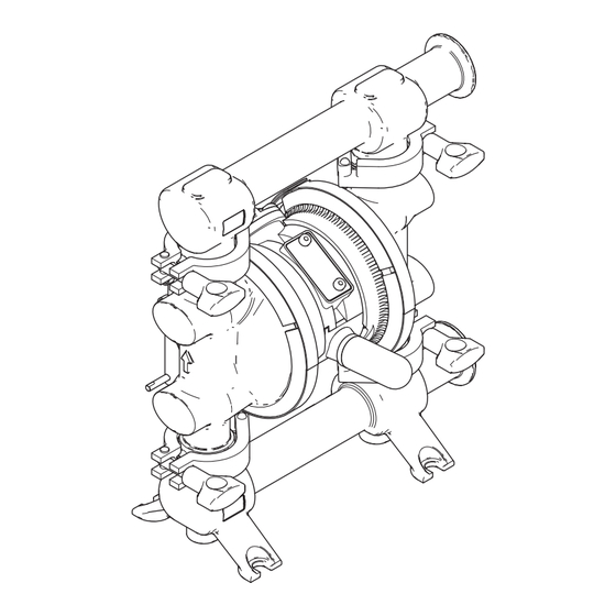
Verder HI-CLEAN VA-H20
Diaphragm Pumps
For use in sanitary applications. For professional use only.
Important Safety Instructions
Read all warnings and instructions in this
manual. Save these instructions.
6.9 bar (0.7 MPa, 100 psi) Maximum Fluid Working Pressure
6.9 bar (0.7 MPa, 100 psi) Maximum Air Input Pressure
ti17529a
819.0416
Rev. L
EN
Advertisement
Table of Contents

Related Manuals for VERDER HI-CLEAN VA-H20


Summary of Contents for VERDER HI-CLEAN VA-H20
- Page 1 Instructions/Parts List Verder HI-CLEAN VA-H20 819.0416 Diaphragm Pumps Rev. L For use in sanitary applications. For professional use only. Important Safety Instructions Read all warnings and instructions in this manual. Save these instructions. 6.9 bar (0.7 MPa, 100 psi) Maximum Fluid Working Pressure 6.9 bar (0.7 MPa, 100 psi) Maximum Air Input Pressure...
-
Page 2: Table Of Contents
Contents Models ........3 Maintenance ......12 Available Configurations . -
Page 3: Models
Models Models Sample Configuration Number: VA-H20 SP ST TF TF T2 FD VA-H 20 ST TF TF Pump Model Size Fluid Section Seats and Balls Diaphragms Connections Pump and Air Section O-Rings Style NOTE: Some combinations are not possible. Please check with your local supplier or on www.verderair.com. Pump Fluid Section and Air Section Seats and O-Rings... -
Page 4: Warnings
Warnings Warnings The following warnings are for the setup, use, grounding, maintenance, and repair of this equipment. The exclama- tion point symbol alerts you to a general warning and the hazard symbols refer to procedure-specific risks. When these symbols appear in the body of this manual or on warning labels, refer back to these Warnings. Product-specific hazard symbols and warnings not covered in this section may appear throughout the body of this manual where applicable. - Page 5 Warnings WARNING EQUIPMENT MISUSE HAZARD Misuse can cause death or serious injury. • Do not operate the unit when fatigued or under the influence of drugs or alcohol. • Do not exceed the maximum working pressure or temperature rating of the lowest rated system component.
-
Page 6: Installation
The typical installation shown in F . 2, page 8, is only a guide for selecting and installing system com- ponents. Contact your Verder representative for assistance in planning a system to suit your needs. • Reference numbers and letters in parentheses refer to the callouts in the figures. -
Page 7: Mounting
Installation Mounting accessories and use it to isolate them during cleaning and repair. NOTICE Pump exhaust air may contain contaminants that can contaminate the fluid supply. Ventilate to a remote In the step below, do not connect the quick-disconnect area. See Air Exhaust Ventilation on page 10. coupler (D) on the air hose to the mating fitting on the •... -
Page 8: Fluid Outlet Line
Installation Fluid Outlet Line 1. Use flexible grounded fluid hoses (J). 2. For best sealing results, use an appropriate stan- dard tri-clamp-style or DIN-style sanitary gasket of a flexible material such as EPDM or Buna-N. A fluid drain valve (G) is required to relieve pressure in 3. -
Page 9: Changing The Orientation Of The Fluid Inlet And Outlet Ports
Installation Changing the Orientation of the Fluid Inlet and Outlet Ports The pump is shipped with the ports facing the same direction. To reverse the orientation of the ports: 1. Remove the clamps (12) holding the inlet and/or outlet manifold to the covers. NOTE: Inspect the o-rings and replace if necessary. -
Page 10: Air Exhaust Ventilation
Installation Air Exhaust Ventilation The air exhaust port is 3/8 npt(f). Do not restrict the air exhaust port. Excessive exhaust restriction can cause erratic pump operation. To provide a remote exhaust: To avoid serious injury from explosion or hazardous 1. Remove the muffler (P) from the pump air exhaust fluids: port. -
Page 11: Operation
Operation Operation Pressure Relief Procedure Starting and Adjusting the Pump Follow the Pressure Relief Procedure whenever 1. Be sure the pump is properly grounded. Refer to you see this symbol. Grounding on page 6. 2. Check connections to be sure they are tight. Tighten fluid inlet and outlet connections securely. -
Page 12: Maintenance
Maintenance Maintenance Air Valve Lubrication Tightening Connections The air valve is designed to operate unlubricated, how- Before each use, check all hoses for wear or damage, ever if lubrication is desired, every 500 hours of opera- and replace as necessary. Check to be sure all connec- tion (or monthly) remove the hose from the pump air tions are tight and leak-free. -
Page 13: Troubleshooting
Troubleshooting Troubleshooting 1. Follow the Pressure Relief Procedure, page 11. 2. Check all possible problems and causes before dis- assembling the pump. PROBLEM CAUSE SOLUTION Pump will not cycle, or cycles once Air valve is stuck or dirty. Disassemble and clean air valve. and stops. -
Page 14: Service
Service Service Air Valve NOTE: When instructed to lubricate, apply appropriate waterproof sanitary lubricant. NOTE: Air Valve Repair Kit 819.0662 is available. Parts 6. Lubricate the lapped surface of the valve plate included in the kit are marked †. Use all parts in the kit. (114), and install with the lapped surface facing up. - Page 15 Service Apply appropriate waterproof sanitary lubricant to the threads and inside of clamp. Torque to 7.9 N•m (70 in-lb). Do not use rotary power tools. Air side markings on diaphragm must face housing. Torque to 9-10 N•m (80-90 in-lb) at 100 rpm maximum. Flat side must face toward shaft.
-
Page 16: Ball Check Valve
Service Ball Check Valve Standard Diaphragms NOTE: If your pump uses overmolded PTFE dia- Disassembly phragms, see page 18. NOTE: • PTFE o-rings should be replaced every time mani- Disassembly folds are removed. 1. Follow the Pressure Relief Procedure, page 11. 1. - Page 17 Service Reassembly NOTE: When instructed to grease, apply appropriate waterproof sanitary lubricant. 1. Install the diaphragm assembly on one end of the shaft (105) as follows: a. Install the o-ring (15) on the shaft bolt (14). b. Install the fluid side diaphragm plate (23) on the bolt so the rounded side faces the diaphragm (20).
-
Page 18: Overmolded Ptfe Diaphragms
Service Overmolded PTFE Diaphragms NOTE: If your pump uses standard diaphragms, see page 16. Disassembly 1. Follow the Pressure Relief Procedure, page 11. 2. Remove the manifolds and disassemble the ball ti17651a check valves as explained on page 16. 3. Remove the clamps (6) holding the fluid covers (1) Apply appropriate waterproof sanitary lubricant to the threads and inside of clamp. -
Page 19: Air Center Service
Service NOTE: When you install the clamps in Step 5, orient the center housing so the air inlet is approximately 45° above horizontal and the muffler is approximately hori- zontal. 5. Position the fluid covers (1) and the center housing so the arrows (A) on the covers face the same direc- tion. -
Page 20: Parts
Parts Parts Tri-clamp Model Shown Apply appropriate waterproof sanitary lubricant. Torque to 7.9 N•m (70 in-lb ). Do not use rotary power tools. Air side markings on diaphragm must face housing. Torque to 9-10 N•m (80-90 in-lb ) at 100 rpm maximum. Torque to 4-5 N•m (35-45 in-lb). - Page 21 Parts Ref. Part Description Qty. Ref. Part Description Qty. 24* ----- DIAPHRAGM, TPE backup; 819.0501 COVER, fluid included in kit 859.0299 MANIFOLD, outlet PLATE, diaphragm, air side 819.0500 Tri-clamp models 819.6911 For use with standard dia- 819.0616 DIN models phragms MANIFOLD, inlet 819.0563 For use with overmolded dia-...
-
Page 22: Fluid Section Repair Kits
Fluid Section Repair Kits* Fluid Section Repair Kits* Pump Model Repair Kit Seats Balls Diaphragms O-Rings 810.0824 or 810.0825 819.0609 819.0612 810.0826 or 810.0827 819.0610 819.0613 810.0828 or 810.0829 819.0611 819.0614 Use appropriate waterproof sanitary lubricant. 819.0416... -
Page 23: Dimensions
Dimensions Dimensions 277 mm (10.9 in.) Tri-Clamp Model 163 mm (6.4 in.) Pump Mounting Hole Pattern 323 mm 109 mm (12.7 in.) (4.3 in.) 254 mm 213 mm (10.0 in.) (8.4 in.) 178 mm (7.0 in.) 178 mm ti17653a (7.0 in.) 41 mm (1.6 in.) 152 mm... -
Page 24: Performance Charts
Performance Charts Performance Charts Fluid Outlet Pressure Test Conditions: Pump tested in water with inlet submerged. CYCLES PER MINUTE standard diaphragms; overmolded diaphragms 46; 64 273; 383 91; 128 137; 192 182; 256 228; 319 319; 447 364; 511 (0.7, 100) Fluid Pressure Curves at 7 bar (0.7 MPa, 100 psi ) air pressure at 4.8 bar (0.48 MPa, 70 psi ) air pressure... - Page 25 Performance Charts Air Consumption Test Conditions: Pump tested in water with inlet submerged. CYCLES PER MINUTE standard diaphragms; overmolded diaphragms 46; 64 91; 128 137; 192 182; 256 228; 319 273; 383 319; 447 364; 511 0.84 (30) Air Consumption Curves at 7 bar (0.7 MPa, 100 psi) air pressure 0.70 at 4.8 bar (0.48 MPa, 70 psi) air pressure...
-
Page 26: Technical Data
Technical Data Technical Data Verder VA-H 20 Metric Maximum fluid working pressure 100 psi 0.7 MPa, 7 bar Air pressure operating range* 20-100 psi 0.14-0.7 MPa, 1.4-7 bar Maximum air consumption 28 scfm 0.8 m /minute Air consumption at 70 psi/20 gpm 18 scfm 0.5 m... - Page 27 Technical Data Materials of Construction** Wetted materials on all models 316 SST Wetted material depending on model EPDM, PTFE, Santoprene® (CAUTION: Santoprene® may be used only with non-fatty, non-oily foods or alcohols up to 15%.) Non-wetted external parts 300 series stainless steel, FDA-compliant polypropylene, polyester (labels) Weight All models...
- Page 28 Technical Data Notes 819.0416...
-
Page 29: Customer Services/Guarantee
All VERDER pumps are warranted to the original user against defects in workmanship or materials under normal use (rental use excluded) for two years after purchase date. This warranty does not cover failure of parts or components due to normal wear, damage or failure which in the judgement of VERDER arises from misuse. - Page 30 Customer Services/Guarantee é 819.0416...
Need help?
Do you have a question about the HI-CLEAN VA-H20 and is the answer not in the manual?
Questions and answers