Table of Contents
Advertisement
Quick Links
Advertisement
Table of Contents

Subscribe to Our Youtube Channel
Related Manuals for IFM Electronic Efectorsod PE70 Series


Summary of Contents for IFM Electronic Efectorsod PE70 Series
- Page 1 Operating instructions Pressure sensor PE70xx...
-
Page 2: Table Of Contents
Contents 1 Preliminary note ���������������������������������������������������������������������������������������������������3 1�1 Symbols used ������������������������������������������������������������������������������������������������3 2 Safety instructions �����������������������������������������������������������������������������������������������3 3 Functions and features ����������������������������������������������������������������������������������������3 4 Function ���������������������������������������������������������������������������������������������������������������4 4�1 Communication, parameter setting, evaluation ���������������������������������������������4 4�2 Switching function ������������������������������������������������������������������������������������������4 4�3 Diagnostic function ����������������������������������������������������������������������������������������5 5 Installation������������������������������������������������������������������������������������������������������������5 6 Electrical connection ��������������������������������������������������������������������������������������������6 7 Operating and display elements �������������������������������������������������������������������������7 8 Menu ��������������������������������������������������������������������������������������������������������������������8 8�1 Menu structure �����������������������������������������������������������������������������������������������8... -
Page 3: Preliminary Note
11 Factory setting �������������������������������������������������������������������������������������������������16 1 Preliminary note 1.1 Symbols used ► Instruction > Reaction, result […] Designation of pushbuttons, buttons or indications → Cross-reference Important note: Non-compliance can result in malfunctions or interference� 2 Safety instructions • Please read this document prior to set-up of the unit� Ensure that the product is suitable for your application without any restrictions�... -
Page 4: Function
Avoid static and dynamic overpressure exceeding the given overload pressure by taking appropriate measures� The indicated bursting pressure must not be exceeded. Even if the bursting pressure is exceeded only for a short time, the unit may be destroyed. NOTE: Risk of injury! Use in gases at pressures > 25 bar only after contacting the manufacturer ifm�... -
Page 5: 4�3 Diagnostic Function
The width of the window can be set by means of the difference between SPx and rPx� SPx = upper value, rPx = lower value� P = system pressure; HY = hysteresis; FE = window 4.3 Diagnostic function Output 2 is used as diagnostic output based on the DESINA specification if [OU2] = [dESI]� • If there is no fault, the output is switched and carries UB+ (if P-n = PnP) or UB- (if P-n = nPn)�... -
Page 6: Electrical Connection
6 Electrical connection The unit must be connected by a qualified electrician. The national and international regulations for the installation of electrical equipment must be adhered to� Voltage supply to EN50178, SELV, PELV� ► Disconnect power� ► Connect the unit as follows: 2 x p-switching 2 x n-switching Pin 1 Pin 3 Pin 4 (OUT1) • binary switching output pressure monitoring; IO-Link • binary switching output if [OU2] = [Hno], [Hnc], [Fno] or [Fnc] Pin 2 (OUT2) • diagnostic output if [OU2] = [dESI]... -
Page 7: Operating And Display Elements
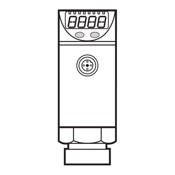
7 Operating and display elements 3 4 5 6 Mode/Enter 1 to 8: Indicator LEDs - LED 1 to LED 4 = system pressure in unit of measurement as indicated on the label� - LED 4 not used for units with 3 adjustable units of measurement� - LEDs 5 and 6 not used�... -
Page 8: Menu
8 Menu 8.1 Menu structure... -
Page 9: 8�2 Explanation Of The Menu
8.2 Explanation of the menu SP1/rP1 Upper / lower limit value for system pressure at which OUT1 switches. SP2/rP2 Upper / lower limit value for system pressure at which OUT2 switches. Output function for OUT1: • Switching signal for the pressure limit values: hysteresis function [H ��] or window function [F ��], either normally open [� no] or normally closed [� nc]� Output function for OUT2: • Switching signal for the pressure limit values: hysteresis function [H ��] or window function [F ��], either normally open [�... -
Page 10: Parameter Setting
9 Parameter setting During parameter setting the unit remains in the operating mode� It continues its monitoring function with the existing parameters until the parameter setting has been completed� 9.1 General parameter setting 3 steps must be taken for each parameter setting: Parameter selection ►... - Page 11 ► Press [Set] and keep it pressed until Mode/Enter Set the valid code no� is displayed� ► Press [Mode/Enter] briefly� On delivery by ifm electronic: no access restriction� ► Press [Set] briefly� > The first parameter of the sub-menu Mode/Enter Set is displayed (here: [Uni])�...
-
Page 12: 9�2 Configuring The Display (Optional)
9.2 Configuring the display (optional) ► Select [Uni] and set the unit of of measurement: - [bar], [mbar], [MPa], [kPa], [PSI], for PE7009 in addition [inHg]� ► Select [diS] and set update rate and orientation of the display: - [d1]: Update of the measured value every 50 ms� - [d2]: Update of the measured value every 200 ms�... -
Page 13: 9�4 User Settings (Optional)
9.4 User settings (optional) 9.4.1 Setting of a time delay for the switching signals [dS1] / [dS2] = switch-on delay for OUT1 / OUT2. [dr1] / [dr2] = switch-off delay for OUT1 / OUT2. ► Select [dS1], [dS2], [dr1] or [dr2] and set a value between 0�1 and 50 s (at 0�0 the delay time is not active)� 9.4.2 Setting of the output logic for the switching outputs ►... -
Page 14: Operation
10 Operation After power on, the unit is in the Run mode (= normal operating mode)� It carries out its measurement and evaluation functions and provides output signals accor- ding to the set parameters� Operating indications → chapter 7 Operating and display elements. 10.1 Reading of the set parameters ►... -
Page 15: 10�3 Setting Ranges
10.3 Setting ranges SP1 / SP2 rP1 / rP2 ΔP 1�0 100�0 0�5 99�5 0�5 1450 1440 0�10 10�00 0�05 9�95 0�05 0�2 25�0 0�1 24�9 0�1 0�02 2�50 0�01 2�49 0�01 -0�90 10�00 -0�95 9�95 0�05 -0�090 1�000 -0�095 0�995 0�005 0�02... - Page 16 11 Factory setting Factory setting User setting 25% VMR* 23% VMR* 75% VMR* 73% VMR* bAr / mbAr * = the indicated percentage of the final value of the measuring range (VMR) of the corresponding sensor in bar / mbar is set� More information at www�ifm�com...
Need help?
Do you have a question about the Efectorsod PE70 Series and is the answer not in the manual?
Questions and answers