Table of Contents
Advertisement
Quick Links
Advertisement
Table of Contents

Related Manuals for IFM Electronic PI7093


Summary of Contents for IFM Electronic PI7093
- Page 1 Operating instructions Electronic pressure sensor PI709x...
-
Page 2: Table Of Contents
Contents 1 Preliminary note ���������������������������������������������������������������������������������������������������3 1�1 Symbols used ������������������������������������������������������������������������������������������������3 2 Safety instructions �����������������������������������������������������������������������������������������������3 3 Functions and features ����������������������������������������������������������������������������������������4 3�1 Applications ���������������������������������������������������������������������������������������������������4 4 Function ���������������������������������������������������������������������������������������������������������������4 4�1 Processing of the measured signals ��������������������������������������������������������������4 4�2 Pressure monitoring / switching function �������������������������������������������������������5 4�3 Pressure monitoring/ analogue function ��������������������������������������������������������5 4�4 Diagnostic function ����������������������������������������������������������������������������������������7 5 Installation������������������������������������������������������������������������������������������������������������8 6 Electrical connection ������������������������������������������������������������������������������������������10... -
Page 3: Preliminary Note
10 Operation ���������������������������������������������������������������������������������������������������������19 10�1 Read the set parameter values �����������������������������������������������������������������19 10�2 Fault indication ������������������������������������������������������������������������������������������19 10�3 Cleaning of the filter cover �������������������������������������������������������������������������20 11 Scale drawing �������������������������������������������������������������������������������������������������21 12 Technical data ��������������������������������������������������������������������������������������������������21 12�1 Setting ranges �������������������������������������������������������������������������������������������23 13 Factory setting �������������������������������������������������������������������������������������������������24 1 Preliminary note 1.1 Symbols used ►... -
Page 4: Functions And Features
3 Functions and features The pressure sensor detects the system pressure of machines and installations� 3.1 Applications Type of pressure: relative pressure Permissible Order no. Measuring range Bursting pressure overload pressure PI7093 -1���25 -14�4���362�7 1 450 5 070 PI7094 -1���10 -14�5���145 2 175 PI7096 -0�124���2�5... -
Page 5: 4�4 Diagnostic Function
• Window function / normally open: [OUx] = [Fno] (→ fig. 2). • Window function / normally closed: [OUx] = [Fnc] (→ fig. 2). The width of the window can be set by means of the distance between SPx and rPx� SPx = maximum value, rPx = minimum value� P = system pressure; HY = hysteresis; FE = window 4.3 Diagnostic function Output 1 is used as a diagnostic output according to DESINA specification if OU1 = dESI�... -
Page 6: Installation
5 Installation Ensure that no pressure is applied to the installation while mounting or removing the sensor� Please note: Display „0%“ does not mean that the system is free of pressure! Horizontal mounting recommended for high medium temperatures� Aseptoflex adapters ensure that the sensor can be connected to different process connections�... - Page 7 Mounting the Aseptoflex adapter ► Slightly grease the threads and sealing areas of the sensor and adapter with lubricating paste (D)� The paste must be suitable and approved for the application and compatible with the elastomers used� Recommendation: Klüber paste UH1 84-201 with USDA-H1 approval for the food industry�...
-
Page 8: Electrical Connection
6 Electrical connection The unit must be connected by a qualified electrician� The national and international regulations for the installation of electrical equipment must be adhered to� Voltage supply to EN50178, SELV, PELV� For units with cULus approval and the scope of validity cULus: The device shall be supplied from an isolating transformer having a secondary Listed fuse rated as noted in the following table�... -
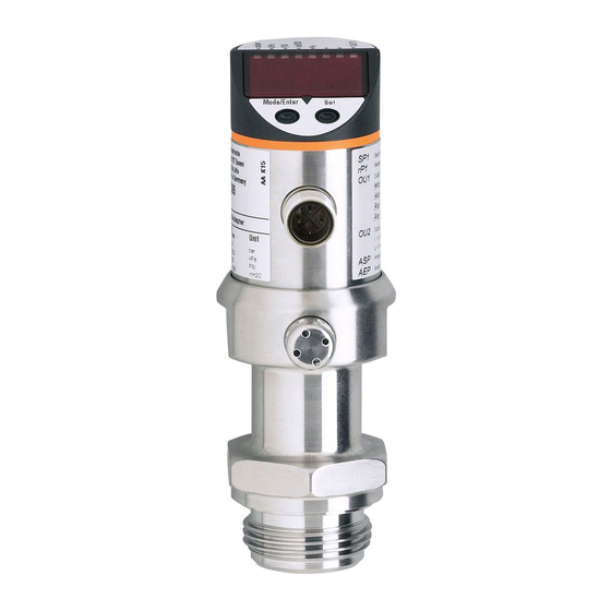
Page 9: Operating And Display Elements
7 Operating and display elements 3 4 5 6 Mode/Enter 1 to 8: Indicator LEDs - LED 1 to LED 6 = system pressure in unit of measurement as indicated on the label� LED 7, LED 8 = switching state of the respective output 9: Alphanumeric display, 4 digits - Indication of the current system pressure�... -
Page 10: Menu
8 Menu 8.1 Menu structure... -
Page 11: 8�2 Menu Explanation
8.2 Menu explanation SP1/rP1 Maximum / minimum value for system pressure, at which output 1 changes its switching status� Output function for OUT1: • Switching signal for the limit values: hysteresis function [H ��] or window function [F ��], normally open [� no] or normally closed [� nc] each� • Diagnostic signal [dESI]�... -
Page 12: Parameter Setting
9 Parameter setting During the parameter setting process the unit remains in the operating mode� It continues its monitoring function with the existing parameters until parameter setting has been terminated� 9.1 Parameter setting general Each parameter setting requires 3 steps: Selecting parameter ►... - Page 13 ► Press [Set] and keep it pressed until the valid code no� is displayed� ► Press [Mode/Enter] briefly� Delivery by ifm electronic: no access restriction� • Locking / unlocking The unit can be locked electronically to prevent unintentional wrong settings�...
-
Page 14: 9�2 Configuring The Display (Optional)
9.2 Configuring the display (optional) ► Select [Uni] and set the unit of measurement: - [bAr], - [MPA], [kPA], - [PSI], - [InHO] (only PI7096), - [mWS] (only PI7096)� ► Select [SELd] and set the display mode: - [P]: Pressure in the unit set in Uni� - [P%]: percentage value (pressure in % of the set scaling of the analogue output�... -
Page 15: 9�3�2 Setting The Switching Limits
9.3.2 Setting the switching limits ► Select [SP1] / [SP2] and set the value at which the output switches� ► Select [rP1] / [rP2] and set the value at which the output switches back� rPx is always lower than SPx� The unit only accepts values which are lower than SPx�... -
Page 16: 9�5 Service Functions
9.4.4 Setting the damping for the switching outputs ► Select [dAP] and set value between 0�1 and 100�0 s (at 0�0 = [dAP] is not active)� dAP value = response time between pressure change and change of the switching status in seconds� [dAP] influences the switching frequency: f = 1 ÷... -
Page 17: 10�2 Fault Indication
10.2 Fault indication [OL] Overload pressure (measuring range exceeded)� [UL] Underpressure range (measuring range below the minimum value)� [SC1] Short circuit in OUT1�* [SC2] Short circuit in OUT2�* [SC] Short circuit in both switching outputs�* [Err] Internal fault, invalid input� *The output concerned is switched off as long as the short circuit exists�... -
Page 18: Scale Drawing
11 Scale drawing Dimensions are in millimeters 1: display 2: LED’s 3: programming button 4: Aseptoflex sealing edge 5: Aseptoflex thread 12 Technical data Operating voltage [V] ������������������������������������������������������������������������������������������� 18���32 DC Current consumption [mA] ��������������������������������������������������������������������������������������������� < 50 Current rating [mA] ��������������������������������������������������������������������������������������������������������� 250 Short-circuit / reverse polarity / overload protection, integrated watchdog Voltage drop [V] ����������������������������������������������������������������������������������������������������������������<... - Page 19 Accuracy / deviation (in % of the span) - Characteristics deviation (linearity� incl� hysteresis and repeatability) ����������������������������������������������������������������������������������������������������������< ± 0�2 - Linearity ������������������������������������������������������������������������������������������������������������������< ± 0�15 - Hysteresis ���������������������������������������������������������������������������������������������������������������< ± 0�15 - Repeatability (with temperature fluctuations < 10 K) ������������������������������������������������< ± 0�1 - Long-term stability (in % of the span per year)���������������������������������������������������������<...
- Page 20 12.1 Setting ranges SP1 / SP2 rP1 / rP2 ΔP -0�96 25�00 -1�00 24�96 0�02 -13�8 362�7 -14�4 362�1 0�3 -0�096 2�500 -0�100 2�496 0�002 -0�98 10�00 -1�00 9�98 0�01 -14�2 145�0 -14�5 144�7 0�1 0�098 1�000 -0�100 0�998 0�001 -0�120 2�500 -0�124...
-
Page 21: Factory Setting
13 Factory setting Factory setting User setting 25% VMR* 23% VMR* 75% VMR* 73% VMR* COF / tCOF SELd * = the indicated percentage of the final value of the measuring range (VMR) of the corresponding sensor in bar is set� More information at www�ifm�com...
Need help?
Do you have a question about the PI7093 and is the answer not in the manual?
Questions and answers