Table of Contents
Advertisement
Advertisement
Table of Contents

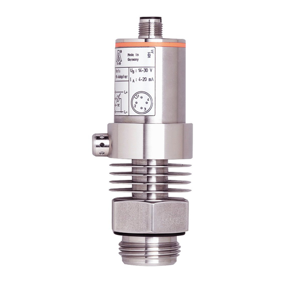
Summary of Contents for IFM Electronic Efectorsod PM2053
- Page 1 Operating instructions Electronic pressure sensor PM205x...
-
Page 2: Table Of Contents
Contents 1 Preliminary note ���������������������������������������������������������������������������������������������������3 1�1 Symbols used ������������������������������������������������������������������������������������������������3 2 Safety instructions �����������������������������������������������������������������������������������������������3 3 Functions and features ����������������������������������������������������������������������������������������4 3�1 Applications ���������������������������������������������������������������������������������������������������4 4 Function ���������������������������������������������������������������������������������������������������������������5 4�1 Processing of the measured signals ��������������������������������������������������������������5 5 Installation������������������������������������������������������������������������������������������������������������6 6 Electrical connection ��������������������������������������������������������������������������������������������7 7 Operation �������������������������������������������������������������������������������������������������������������8 7�1 Cleaning of the filter cover �����������������������������������������������������������������������������8 8 Parameter setting ������������������������������������������������������������������������������������������������9 8�1 Adjustable parameters �����������������������������������������������������������������������������������9... -
Page 3: Preliminary Note
1 Preliminary note 1.1 Symbols used ► Instruction > Reaction, result […] Designation of buttons, switches or indications → Cross-reference Important note Non-compliance can result in malfunctions or interference� 2 Safety instructions • Read this ducument before installing the unit� Ensure that the product is suit- able for your application without any restrictions�... -
Page 4: Functions And Features
3 Functions and features The pressure sensor detects the system pressure of machines and installations� 3.1 Applications Type of pressure: relative pressure Bestell- Zulässiger Messbereich Berstdruck nummer Überdruck PM2053 -1���25 -15���363 1 450 5 070 PM2054 -0,5���10 -7���145 2 175 PM2055 -0,99���4,00 -14,4���58,0... -
Page 5: Function
4 Function 4.1 Processing of the measured signals The unit converts the system pressure into an analogue output signal (4���20 mA)� The measuring range can be scaled to up to 25% of the finalvalue of the measur- ing range� • By setting the parameter ASP you define the measured value at which the output signal is 4 mA�... -
Page 6: Installation
5 Installation Ensure that no pressure is applied to the installation while mounting or removing the sensor� Aseptoflex adapters ensure that the sensor can be connected to different process connections� (The adapters have to be ordered separately as accessories�) Mounting operation: ►... -
Page 7: Electrical Connection
► Screw the sensor into the adapter until it is hand-tight� Do not damage the sealing chamfers� ► Clamp sensor and adapter into a clamping device (D)� Tighten the clamping device only slightly so that the adapter does not warp� The sealing chamfers (E) must not be damaged�... -
Page 8: Operation
► Disconnect power� ► Connect the unit as follows: 2 wire connection 3 wire connection n.c. n.c. n.c. Core colours of ifm sockets: 1 = BN (brown), 2 = WH (white), 3 = BU (blue), 4 = BK (black) 7 Operation After power on of the supply voltage the unit is in the Run mode (= normal opera- tion)�... -
Page 9: Parameter Setting
The sensor is sufficiently protected against harsh ambient conditions (protection IP 67)� The protection rating can be increased by a special accessory (order no� E30043)� 8 Parameter setting ► Connect the sensor to a PC via IO-Link-Interface (order no� E30396)� ►... -
Page 10: Scale Drawing
Setting of the display d1 / d2 / d3 = update of the measured value every 50ms / 200ms / 600ms� The update interval only refers to the display� ph = display of the measured peak value remains for a short time (peak hold)� 9 Scale drawing M12 x1 Dimensions are in mm... -
Page 11: Technical Data
10 Technical data Operating voltag [V] ��������������������������������������������������������������������������������������������� 14���30 DC Operating voltage for EPS interface with sensor [V] ���������������������������������������� 15�5���30 DC reverse polarity / overload protection Analogue output ������������������������������������������������������������������������������������������������ 4���20 mA Max. load [Ω] ������������������������������������������������������������������������������������������������� (Ub - 13) x 50 Min� response time analog output [ms] ������������������������������������������������������������������������������ 3 Accuracy / deviation (in % of the span) - Characteristics deviation (linearity�... -
Page 12: 10�1 Setting Ranges
10.1 Setting ranges ΔP -1�0 18�8 5�3 25�0 0�1 -0�10 1�88 0�53 2�50 0�01 -0�50 7�49 2�00 9�99 0�01 -0�99 1�00 0�26 4�00 0�01 -14�4 14�5 3�7 58�0 0�1 -0�13 1�88 0�50 2�50 0�01 -1�8 27�2 7�3 36�3 0�1 mbar -0�7 10�9 2�9...


Need help?
Do you have a question about the Efectorsod PM2053 and is the answer not in the manual?
Questions and answers