Table of Contents
Advertisement
Advertisement
Table of Contents

Subscribe to Our Youtube Channel
Related Manuals for IFM Electronic PN72 Series


Summary of Contents for IFM Electronic PN72 Series
- Page 1 Operating instructions Electronic pressure sensor PN72xx PN73xx PN76xx...
-
Page 2: Table Of Contents
Contents 1 Preliminary note ���������������������������������������������������������������������������������������������������4 1�1 Symbols used ������������������������������������������������������������������������������������������������4 2 Safety instructions �����������������������������������������������������������������������������������������������4 3 Functions and features ����������������������������������������������������������������������������������������5 3�1 Applications ���������������������������������������������������������������������������������������������������5 4 Function ���������������������������������������������������������������������������������������������������������������7 4�1 Communication, parameter setting, evaluation ���������������������������������������������7 4�2 Switching function ������������������������������������������������������������������������������������������7 4�3 IO-Link �����������������������������������������������������������������������������������������������������������8 5 Installation������������������������������������������������������������������������������������������������������������9 6 Electrical connection ��������������������������������������������������������������������������������������������9 7 Operating and display elements ������������������������������������������������������������������������10 8 Menu ������������������������������������������������������������������������������������������������������������������... - Page 3 10 Operation ���������������������������������������������������������������������������������������������������������21 10�1 Read set parameters ���������������������������������������������������������������������������������21 10�2 Self-diagnosis / error indications ���������������������������������������������������������������22 11 Technical data and scale drawing ��������������������������������������������������������������������24 11�1 Setting ranges ��������������������������������������������������������������������������������������������24 11�2 Further technical data ��������������������������������������������������������������������������������25 12 Factory setting �������������������������������������������������������������������������������������������������25...
-
Page 4: Preliminary Note
1 Preliminary note 1.1 Symbols used ► Instructions > Reaction, result […] Designation of keys, buttons or indications → Cross-reference Important note Non-compliance can result in malfunction or interference� Information Supplementary note� 2 Safety instructions • Please read this document prior to set-up of the unit� Ensure that the product is suitable for your application without any restrictions�... -
Page 5: Functions And Features
3 Functions and features The device monitors the system pressure of machines and installations� 3.1 Applications Type of pressure: relative pressure Permissible Bursting pres- Order no. Measuring range overpressure * sure Pressure sensors with internal thread 1/4 - 18 NPT PN7270 0…5800 0���400... - Page 6 Avoid static and dynamic overpressure exceeding the specified overload pressure by taking appropriate measures� The indicated bursting pressure must not be exceeded� Even if the bursting pressure is exceeded only for a short time, the unit may be destroyed. ATTENTION: Risk of injury! Pressure Equipment Directive (PED): The units comply with section 3, article (3) of the Directive 97/23/EC and are designed and manufactured for "non-superheated liquids"...
-
Page 7: Function
4 Function • The unit displays the current system pressure� • It generates output signals according to the operating mode and the parameter setting� • It moreover provides the process data via IO-Link� • The unit is laid out for fully bidirectional communication� So, the following options are possible: - Remote display: reading and display of the current system pressure�... -
Page 8: 4�3 Io-Link
P = system pressure; HY = hysteresis; FE = window 4.3 IO-Link General information This unit has an IO-Link communication interface which requires an IO-Link- capable module (IO-Link master) for operation� The IO-Link interface enables direct access to the process and diagnostic data and provides the possibility to set the parameters of the unit during operation�... -
Page 9: Installation
5 Installation Before installing and removing the unit: Make sure that no pressure is applied to the system� ► Insert the unit in a process connection with a suitable thread� ► Tighten firmly� Tightening Torque 1/4-18 NPT threads: 2���3 turns after finger tightened� To ensure leak-free joints for NPT threads, sealants and lubricants com- monly used in the industry should be used�... -
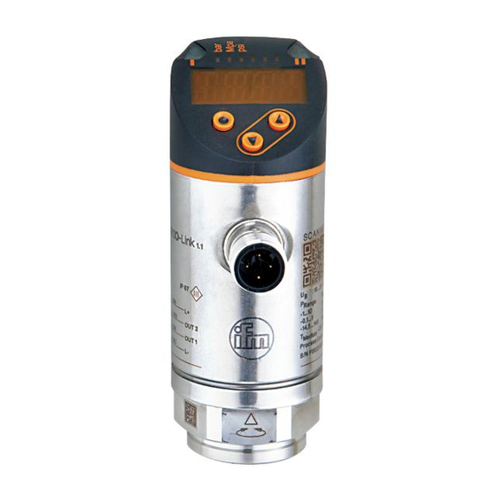
Page 10: Operating And Display Elements
7 Operating and display elements 1 to 8: Indicator LEDs LED 1 Switching status OUT1 (lights when output 1 is switched)� LED 8 Switching status OUT2 (lights when output 2 is switched)� LEDs System pressure in the indicated unit of measurement� 2 - 7 9: [Enter] button [●] - Selection of the parameters and acknowledgement of the parameter values�... -
Page 11: Menu
8 Menu 8.1 Menu structure: Main menu Menu items highlighted in grey e�g� [ FH1 ] are only active when assigned parameters have been selected�... -
Page 12: 8�2 Explanation Of The Menu
8.2 Explanation of the menu 8.2.1 Explanation of the menu level 1 SPx/rPx Upper / lower limit value for system pressure at which OUT1 switches with hysteresis setting� SPx/rPx is displayed if the parameter [Hno] or [Hnc] for OUTx was set in the extended functions "EF" menu� FHx/FLx Upper / lower limit value for system pressure at which OUT1 switches with window setting�... -
Page 13: Parameter Setting
9 Parameter setting During parameter setting the unit remains in the operating mode� It continues to monitor with the existing parameters until the parameter setting has been completed� 9.1 Parameter setting in general 3 steps must be taken for each parameter setting: Select parameter ►... - Page 14 If [C�Loc] is displayed when an attempt is made to modify a parameter value, an IO-Link communication is active (temporary locking)� If [S�Loc] is displayed, the sensor is permanently locked via software� This locking can only be removed using a parameter setting software� •...
- Page 15 • Locking / unlocking The unit can be locked electronically to prevent unintentional settings� ► Make sure that the unit is in the normal operating mode� ► Press [▲] + [▼] simultaneously for 10 s� > [Loc] is displayed� 10 s During operation: [Loc] is briefly displayed if you try to change parameter values�...
-
Page 16: 9�2 Configure Display (Optional)
9.2 Configure display (optional) ► Select [Uni] and set the unit of measurement: - [Psi], - [bAr], [mbAr], - [MPA], [kPA], - [inHG] The selectable units of measurement depend on the respec- tive unit� ► Select [diS] and set the update rate and orientation of the display: - [d1]: update of the measured values every 50 ms�... -
Page 17: 9�3�3 Define Switching Limits For The Window Function
9.3.3 Define switching limits for the window function ► [ou1] /[ou2] must be set as [Fno] or [Fnc]� ► Select [FH1] / [FH2] and set the upper limit value� ► Select [FL1] / [FL2] and set the lower limit value� FLx is always lower than FHx�... -
Page 18: 9�4�5 Reset All Parameters To Factory Setting
9.4.5 Reset all parameters to factory setting ► Select [rES]� ► Press [●]. ► Press and hold [▲] or [▼] until [----] is displayed� ► Briefly press [●]. We recommend noting down your own settings before carrying out a reset (→... -
Page 19: 9�4�7 Graphical Depiction Of The Colour Change Of The Display
9.4.7 Graphical depiction of the colour change of the display Display colour change for the parameters Display colour change for the parame- [r1ou] / [r2ou], mode hysteresis function ters [G1ou] / [G2ou], mode hysteresis function OUT1/ OUT1/ OUT2 OUT2 Measured value > switch point OUT1/OUT2; Measured value >... - Page 20 Display colour change for the parameters Display colour change for the parameters [r-12], mode hysteresis function [G-12], mode hysteresis function OUT2 OUT2 OUT1 OUT1 Measured value between OUT1 and OUT2; Measured value between OUT1 and OUT2; Display = red Display = green Display colour change for the parameters Display colour change for the parameters [r-12], mode window function...
-
Page 21: Operation
Display colour change with parameter [r-cF] Display colour change with parameter [G-cF] independent of OUT1 / OUT2 independent of OUT1 / OUT2� Measured value between cFL and cFH; Measured value between cFL and cFH; Display = red Display = green Colour change display green Colour change display red Initial value of the measuring range... -
Page 22: 10�2 Self-Diagnosis / Error Indications
10.2 Self-diagnosis / error indications The unit has many self-diagnostic options� • It monitors itself automatically during operation� • Warnings and faults are displayed (even if the display is deactivated), in addition they are available via IO-Link� none Supply voltage too low� ►... - Page 23 Process value too low ► Check / increase system (value below measuring pressure / select unit with range)� corresponding measuring range� Internal fault / malfunc- ► Contact the manufacturer� flashes tion� The respective output remains deactivated as long as the excessive current / short circuit continues�...
-
Page 24: Technical Data And Scale Drawing
11 Technical data and scale drawing 11.1 Setting ranges SP1 / SP2 rP1 / rP2 ΔP 5800 5780 PN7270 PN7370 PN7670 0�4 0�2 39�8 0�2 3620 3600 PN7271 PN7671 0�2 0�1 24�9 0�1 1450 1445 PN7292 PN7392 0�5 99�5 0�5 PN7692 0�1 0�05... -
Page 25: 11�2 Further Technical Data
11.2 Further technical data Further technical data and scale drawing at www.ifm.com → Data sheet search → Enter the article number. 12 Factory setting Factory setting User setting 25% VMR * 23% VMR * 75% VMR * 73% VMR * 0.06 colr * = The indicated percentage of the final value of the measuring range (VMR) of the...
Need help?
Do you have a question about the PN72 Series and is the answer not in the manual?
Questions and answers