
Related Manuals for IFM Electronic PN7000


Summary of Contents for IFM Electronic PN7000
- Page 1 Operating instructions Pressure sensor PN70xx Tel: +44 (0)191 490 1547 Fax: +44 (0)191 477 5371 Email: northernsales@thorneandderrick.co.uk Website: www.heattracing.co.uk www.thorneanderrick.co.uk...
-
Page 2: Table Of Contents
Contents 1 Preliminary note ���������������������������������������������������������������������������������������������������3 1�1 Symbols used ������������������������������������������������������������������������������������������������3 2 Safety instructions �����������������������������������������������������������������������������������������������3 3 Functions and features ����������������������������������������������������������������������������������������4 4 Function ���������������������������������������������������������������������������������������������������������������5 4�1 Communication, parameter setting, evaluation ���������������������������������������������5 4�2 Switching function ������������������������������������������������������������������������������������������5 4�3 Diagnostic function ����������������������������������������������������������������������������������������6 5 Installation������������������������������������������������������������������������������������������������������������6 6 Electrical connection ��������������������������������������������������������������������������������������������7 7 Operating and display elements �������������������������������������������������������������������������8 8 Menu ��������������������������������������������������������������������������������������������������������������������9 8�1 Menu structure �����������������������������������������������������������������������������������������������9... -
Page 3: Preliminary Note
13 Factory setting �������������������������������������������������������������������������������������������������19 1 Preliminary note 1.1 Symbols used ► Instruction > Reaction, result […] Designation of pushbuttons, buttons or indications → Cross-reference Important note: Non-compliance can result in malfunctions or interference� 2 Safety instructions • Please read this document prior to set-up of the unit� Ensure that the product is suitable for your application without any restrictions�... -
Page 4: Functions And Features
• When the damping device is removed the damping device can become unus- able� • When the damping device is removed the unit can no longer be used under UL conditions� If you have any questions, please contact ifm electronic’s sales specialists�... -
Page 5: Function
4 Function 4.1 Communication, parameter setting, evaluation • The unit displays the current process value� • It generates 2 output signals according to the parameter setting� OUT1 • Switching signal for process value; IO-Link� 2 options OUT2 • Switching signal for process value� • Diagnostic signal (output 2 is inactive in case of a fault)�... -
Page 6: 4�3 Diagnostic Function
P = system pressure; HY = hysteresis; FE = window 4.3 Diagnostic function Output 2 is used as diagnostic output based on the DESINA specification if [OU2] = [dESI]� • If there is no fault, the output is switched and carries UB+ (if P-n = PnP) or UB- (if P-n = nPn)�... -
Page 7: Electrical Connection
6 Electrical connection The unit must be connected by a qualified electrician� The national and international regulations for the installation of electrical equipment must be adhered to� Voltage supply to EN50178, SELV, PELV� ► Disconnect power� ► Connect the unit as follows: 2 x p-switching 2 x n-switching 1 BN... -
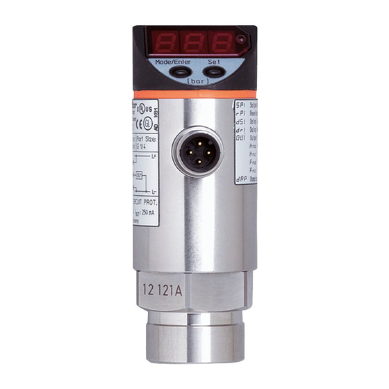
Page 8: Operating And Display Elements
7 Operating and display elements 3 4 5 6 Mode/Enter 1 to 8: Indicator LEDs - LED 1 to LED 4 = system pressure in unit of measurement as indicated on the label� - LED 4 not used for units with 3 adjustable units of measurement� - LEDs 5 and 6 not used�... -
Page 9: Menu
8 Menu 8.1 Menu structure... -
Page 10: 8�2 Explanation Of The Menu
8.2 Explanation of the menu SP1/rP1 Upper / lower limit value for system pressure at which OUT1 switches� SP2/rP2 Upper / lower limit value for system pressure at which OUT2 switches� OU1 Output function for OUT1: • Switching signal for the pressure limit values: hysteresis function [H ��] or window function [F ��], either normally open [�... -
Page 11: Parameter Setting
9 Parameter setting During parameter setting the unit remains in the operating mode� It continues its monitoring function with the existing parameters until the parameter setting has been completed� 9.1 General parameter setting 3 steps must be taken for each parameter setting: Parameter selection ►... - Page 12 ► Press [Set] and keep it pressed until Mode/Enter Set the valid code no� is displayed� ► Press [Mode/Enter] briefly� On delivery by ifm electronic: no access restriction� ► Press [Set] briefly� > The first parameter of the sub-menu Mode/Enter Set is displayed (here: [Uni])�...
-
Page 13: 9�2 Configuring The Display (Optional)
9.2 Configuring the display (optional) ► Select [Uni] and set the unit of of measurement: - [bar], [mbar], [MPa], [kPa], [PSI], for PN7007 and PN7009 in addition [inHg]� ► Select [diS] and set update rate and orientation of the display: - [d1]: Update of the measured value every 50 ms�... -
Page 14: 9�4 User Settings (Optional)
9.4 User settings (optional) 9.4.1 Setting of a time delay for the switching signals [dS1] / [dS2] = switch-on delay for OUT1 / OUT2� [dr1] / [dr2] = switch-off delay for OUT1 / OUT2� ► Select [dS1], [dS2], [dr1] or [dr2] and set a value between 0�2 and 50 s (at 0�0 the delay time is not active)�... -
Page 15: Operation
10 Operation After power on, the unit is in the Run mode (= normal operating mode)� It carries out its measurement and evaluation functions and provides output signals accord- ing to the set parameters� Operating indications → chapter 7 Operating and display elements. 10.1 Reading of the set parameters ►... -
Page 16: Scale Drawing
11 Scale drawing 21,5 Dimensions are in millimeters = dimensions for PN7000 and PN7060 1: display 2: LED’s 3: programming button 12 Technical data Operating voltage [V] ������������������������������������������������������������������������������������������18���36 DC Current consumption [mA] ��������������������������������������������������������������������������������������������� < 50 Current rating per switching output [mA] ������������������������������������������������������������������������ 250 Reverse polarity protection, overload protection �������������������������������������������������... - Page 17 EN 61000-4-5 Surge: ����������������������������������������������������������������������������������0�5 / 1 KV EN 61000-4-6 HF conducted: ���������������������������������������������������������������������������� 10 V to EN50178, SELV, PELV in addition PTFE for PN7003���PN7009 for PN7000���PN7002, PN7060 for PN7003���PN7009 BFSL = Best Fit Straight Line / LS = Limit Value Setting...
-
Page 18: 12�1 Setting Ranges
12.1 Setting ranges SP1 / SP2 rP1 / rP2 ΔP 5790 5760 0�4 40�0 0�2 39�8 0�2 3620 3600 0�2 25�0 0�1 24�9 0�1 1�0 100�0 0�5 99�5 0�5 1450 1440 0�10 10�00 0�05 9�95 0�05 0�2 25�0 0�1 24�9 0�1 0�02 2�50... - Page 19 SP1 / SP2 rP1 / rP2 ΔP 8700 8650 0�6 60�0 0�3 59�7 0�3 ΔP = increments 13 Factory setting Factory setting User setting 25% VMR* 23% VMR* 75% VMR* 73% VMR* bAr / mbAr * = the indicated percentage of the final value of the measuring range (VMR) of the corresponding sensor in bar / mbar is set�...
Need help?
Do you have a question about the PN7000 and is the answer not in the manual?
Questions and answers