Table of Contents
Advertisement
Advertisement
Table of Contents

Subscribe to Our Youtube Channel
Related Manuals for IFM Electronic PN50 Series


Summary of Contents for IFM Electronic PN50 Series
- Page 1 Operating instructions Pressure sensor PN50xx...
-
Page 2: Table Of Contents
Contents 1 Preliminary note ���������������������������������������������������������������������������������������������������3 1�1 Symbols used ������������������������������������������������������������������������������������������������3 2 Safety instructions �����������������������������������������������������������������������������������������������3 3 Functions and features ����������������������������������������������������������������������������������������4 4 Function ���������������������������������������������������������������������������������������������������������������5 4�1 Processing of the measured signals ��������������������������������������������������������������5 4�2 Switching function ������������������������������������������������������������������������������������������5 5 Installation������������������������������������������������������������������������������������������������������������6 6 Electrical connection ��������������������������������������������������������������������������������������������6 7 Operating and display elements �������������������������������������������������������������������������7 8 Menu ��������������������������������������������������������������������������������������������������������������������8 8�1 Menu structure ����������������������������������������������������������������������������������������������8 8�2 Explanation of the menu ��������������������������������������������������������������������������������9... -
Page 3: Preliminary Note
1 Preliminary note 1.1 Symbols used ► Instruction > Reaction, result […] Designation of buttons, switches or indications → Cross-reference Important note Non-compliance can result in malfunctions or interference. 2 Safety instructions • Read this document before installing the unit. Ensure that the product is suita- ble for your application without any restrictions. -
Page 4: Functions And Features
• When the damping device is removed the damping device can become unus- able. • When the damping device is removed the unit can no longer be used under UL conditions, If you have any questions, please contact ifm electronic’s sales specialists. -
Page 5: Function
Function Processing of the measured signals • The unit shows the current system pressure on its display� • It generates 1 output signal according to the parameter setting� OUT1 switching signal for pressure limit values Switching function OUT1 changes its switching state if it is above or below the set switching limits (SP1, rP1)�... -
Page 6: Installation
5 Installation Before mounting and removing the sensor, make sure that no pressure is applied to the system. ► Insert the unit in a G¼ process connection. ► Tighten firmly. 6 Electrical connection The unit must be connected by a qualified electrician. The national and international regulations for the installation of electrical equipment must be adhered to. -
Page 7: Operating And Display Elements
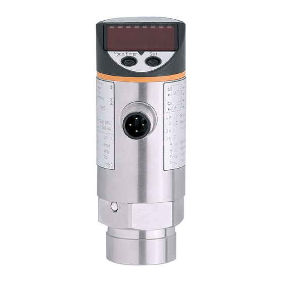
Operating and display elements � � � � � � � � � ���������� ��� �� �� 1 to 8: Indicator LEDs LED 1 to LED 4 = system pressure in unit of measurement as indicated on the label� LED 4 not used for units with 3 adjustable units of measurement� LEDs 5 to 7 not used�... -
Page 8: Menu
Menu Menu structure ��� � � � � � � � � � � � � � � � � � � � � � � � � � � � � � � � � �... -
Page 9: 8�2 Explanation Of The Menu
Explanation of the menu SP1/rP1 Maximum / minimum value for system pressure, at which output 1 changes its switching status� Output function for OUT1: • Switching signal for the limit values: hysteresis function [H ��] or window function [F ��], normally open [� no] or normally closed [� nc] each� Extended functions / Opening menu level 2�... -
Page 10: Parameter Setting
Parameter setting During the parameter setting process the unit remains in the operating mode� It continues its monitoring function with the existing parameters until parameter setting has been terminated� Parameter setting general Each parameter setting requires 3 steps: Selecting parameter ►... - Page 11 ► Press [Set] and hold it pressed until ���������� ��� the valid code no� is shown� ► Then briefly press [Mode/Enter]� Delivery by ifm electronic: no access restriction� ► Press [Set] briefly� > The first parameter of the submenu is ����������...
-
Page 12: 9�2 Configuring The Display (Optional)
Configuring the display (optional) ► Select [Uni] and set the unit of measurement: [bar], [mbar], [MPa], [kPa], [PSI], for PN5007 in addition [inHg]� ► Select [diS] and set update rate and orientation of the display: [d1]: Update of the measured value every 50 ms� [d2]: Update of the measured value every 200 ms�... -
Page 13: 9�5 Service Functions
Service functions 9.5.1 Reading the min./max. values for the system pressure ► Select [HI] or [LO], press [Set] briefly� [HI] = maximum value, [LO] = minimum value� Delete memory: ► Select [HI] or [LO]� ► Press [Set] until [----] is displayed� ►... -
Page 14: Scale Drawing
Scale drawing � � �� �� � ���� �� �� � � � � Dimensions are in millimeters = dimensions for PN5000 1: display 2: LED’s 3: programming button Technical data Operating voltage [V] ����������������������������������������������������������������������������������������� 18���36 DC Current rating [mA] ��������������������������������������������������������������������������������������������������������� 250 Current consumption [mA] ���������������������������������������������������������������������������������������������... - Page 15 Accuracy / deviations (in % of the span) - Accuracy of switch point ����������������������������������������������������������������������������������������� < ± 0�5 - Characteristics deviation ���������������������������������������������������� < ± 0�25 (BFSL) / < ± 0�5 (LS) - Hysteresis ����������������������������������������������������������������������������������������������������������������� < 0�25 - Repeatability (with temperature fluctuations < 10K) ������������������������������������������������ < ± 0�1 - Long-time stability (in% of the span per year) �������������������������������������������������������...
-
Page 16: 12�1 Setting Ranges
12.1 Setting ranges SP1 / SP2 rP1 / rP2 ΔP 5790 5760 0�4 40�0 0�2 39�8 0�2 3620 3600 0�2 25�0 0�1 24�9 0�1 1�0 100�0 0�5 99�5 0�5 1450 1440 0�10 10�00 0�05 9�95 0�05 0�2 25�0 0�1 24�9 0�1 0�02 2�50... -
Page 17: Factory Setting
Factory setting Factory setting User setting 25% VMR* 23% VMR* bAr / mbAr * = the indicated percentage of the final value of the measuring range (VMR) of the corresponding sensor in bar / mbar is set� More information at www�ifm�com...
Need help?
Do you have a question about the PN50 Series and is the answer not in the manual?
Questions and answers