Bosch Dinion2X Installation And Operation Manual
Hide thumbs
Also See for Dinion2X:
- Installation and operation manual (138 pages) ,
- Installation manual (62 pages)

Subscribe to Our Youtube Channel
Related Manuals for Bosch Dinion2X


Summary of Contents for Bosch Dinion2X
- Page 1 Dinion2X IP Camera NBN-498 Installation and Operation Manual This manual downloaded from http://www.manualowl.com...
- Page 2 This manual downloaded from http://www.manualowl.com...
-
Page 3: Table Of Contents
Dinion2X IP Camera Table of Contents | en Table of Contents Safety Safety precautions Important safety instructions Connection in applications FCC & ICES compliance UL certification Bosch notices Copyrights Introduction Features System Information Overview of functions 3.1.1 Progressive scan 3.1.2 Day/Night function 3.1.3... - Page 4 | Table of Contents Dinion2X IP Camera Planning Unpacking System requirements Install players Installation Network (and power) connector Power connector Alarm and relay connector Audio connectors Video service monitor connector Data connector Lens mounting Mounting the camera Using the camera install menu 5.10...
-
Page 5: Dinion2X Ip Camera Table Of Contents | En
Dinion2X IP Camera Table of Contents | en Protected network Connecting to a hardware decoder 7.4.1 Alarm connection Connection established 7.5.1 LIVEPAGE 7.5.2 RECORDINGS 7.5.3 SETTINGS Basic Mode Basic Mode menu tree Device Access 8.2.1 Camera name 8.2.2 Password Date/Time... - Page 6 | Table of Contents Dinion2X IP Camera Audio Camera 9.6.1 Mode 9.6.2 9.6.3 Shutter/AGC 9.6.4 Day/night 9.6.5 Enhance 9.6.6 Color 9.6.7 Installer Options Recording 9.7.1 Storage Management 9.7.2 Recording Profiles 9.7.3 Retention Time 9.7.4 Recording Scheduler 9.7.5 Recording Status Alarm 9.8.1...
-
Page 7: Dinion2X Ip Camera Table Of Contents | En
Dinion2X IP Camera Table of Contents | en 9.11.3 System Overview Operation via the browser 10.1 Livepage 10.1.1 Processor load 10.1.2 Image selection 10.1.3 View Control 10.1.4 Digital I/O 10.1.5 System Log / Event Log 10.1.6 Saving snapshots 10.1.7 Recording video sequences 10.1.8... -
Page 8: Safety
| Safety Dinion2X IP Camera Safety Safety precautions DANGER! High risk: This symbol indicates an imminently hazardous situation such as "Dangerous Voltage" inside the product. If not avoided, this will result in an electrical shock, serious bodily injury, or death. -
Page 9: Important Safety Instructions
Dinion2X IP Camera Safety | en Important safety instructions Read, follow, and retain for future reference all of the following safety instructions. Follow all warnings on the unit and in the operating instructions before operating the unit. Clean only with a dry cloth. Do not use liquid cleaners or aerosol cleaners. -
Page 10: Connection In Applications
| Safety Dinion2X IP Camera Connection in applications Power lines: An outdoor system should not be located in the vicinity of overhead power lines, electrical lights, or power circuits, or where it may contact such power lines or circuits. -
Page 11: Fcc & Ices Compliance
Dinion2X IP Camera Safety | en FCC & ICES compliance FCC & ICES Information (U.S.A. and Canadian Models Only) This equipment has been tested and found to comply with the limits for a Class B digital device, pursuant to part 15 of the FCC Rules. - Page 12 | Safety Dinion2X IP Camera Informations FCC et ICES (modèles utilisés aux États-Unis et au Canada uniquement) Suite à différents tests, cet appareil s'est révélé conforme aux exigences imposées aux appareils numériques de classe B, en vertu de la section 15 du règlement de la Commission fédérale des communications des États-Unis (FCC), et en vertu de la...
-
Page 13: Ul Certification
CERTIFICATIONS WHATSOEVER REGARDING THE PERFORMANCE OR RELIABILITY OF ANY SECURITY OR SIGNALING RELATED FUNCTIONS OF THIS PRODUCT. Disposal - Your Bosch product was developed and manufactured with high-quality material and components that can be recycled and reused. This symbol means that... -
Page 14: Bosch Notices
Bosch notices Video loss Video loss is inherent to digital video recording; therefore, Bosch Security Systems cannot be held liable for any damage that results from missing video information. To minimize the risk of lost digital information, Bosch Security Systems recommends multiple, redundant recording systems, and a procedure to back up all analog and digital information. -
Page 15: Copyrights
Dinion2X IP Camera Safety | en Copyrights The firmware 4.1 uses the fonts "Adobe-Helvetica-Bold-R- Normal--24-240-75-75-P-138-ISO10646-1" and "Adobe- Helvetica-Bold-R-Normal--12-120-75-75-P-70-ISO10646-1" under the following copyright: Copyright 1984-1989, 1994 Adobe Systems Incorporated. Copyright 1988, 1994 Digital Equipment Corporation. Permission to use, copy, modify, distribute and sell this... -
Page 16: Introduction
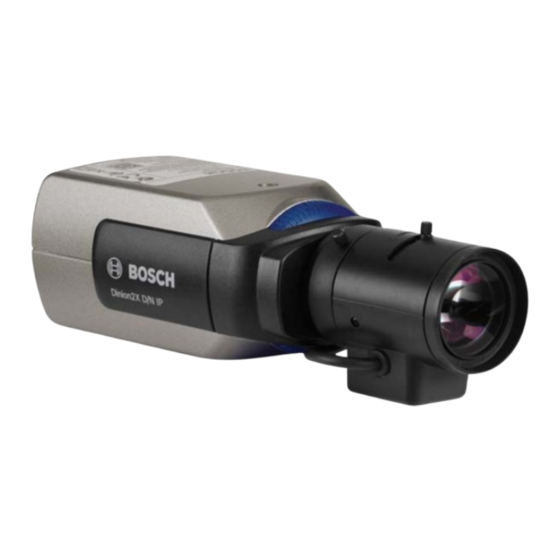
| Introduction Dinion2X IP Camera Introduction Features The Dinion2x IP Day/Night camera is a high-performance, smart surveillance color camera. It incorporates 20-bit digital signal processing and a wide dynamic range sensor for outstanding picture performance under all lighting conditons. - Page 17 Dinion2X IP Camera Introduction | en – Password protection to prevent unauthorized connection or configuration changes – Event-driven, automatic connection (for example, at switch-on and for alarms) – Fast, convenient configuration using the integrated Web server and a browser –...
-
Page 18: System Information
| System Information Dinion2X IP Camera System Information Overview of functions The camera incorporates a network video server. Its primary function is to encode video and control data for transmission over an IP network. With its H.264 encoding, it is ideally suited for IP communication and for remote access to digital video recorders and IP systems. -
Page 19: Tri-Streaming
Dinion2X IP Camera System Information | en 3.1.4 Tri-streaming Tri-streaming allows the data stream to be encoded simultaneously according to three different, individually customized profiles. This creates two full H.264 streams that can serve different purposes and an additional M-JPEG stream. -
Page 20: Power-Over-Ethernet
The browser application has an icon for saving the video images provided by the unit as a file on your computer's hard drive. Clicking this icon stores the video sequences and they can be replayed with the Player from Bosch Security Systems included with the package. 3.1.17... - Page 21 Dinion2X IP Camera System Information | en possible. Configuration settings can be stored as files on a computer and copied from one camera to another. Bosch Security Systems Installation and Operation Manual AR18-10-B006 | v1.1 | 2010.06 This manual downloaded from http://www.manualowl.com...
-
Page 22: Operation With External Systems
| System Information Dinion2X IP Camera Operation with external systems The camera can be used with a variety of Bosch software and hardware systems: – Bosch Video Management System – VIDOS video management software – DiBos 900 Series digital video recorder –... - Page 23 Dinion2X IP Camera System Information | en streams, and is available as software or as a hybrid DVR with additional analog camera and audio inputs. DiBos supports various functions of the camera, such as controlling relays, remote control of peripheral devices, and remote configuration.
-
Page 24: Planning
| Planning Dinion2X IP Camera Planning Unpacking Unpack carefully and handle the equipment with care. The packaging contains: – Dinion2X IP camera – CCD protection cap (mounted on camera) – Power connector – Alarm I/O connector – Data connector –... -
Page 25: System Requirements
VIDOS, Bosch VMS, or DIBOS 900 Series – H.264 compatible hardware decoder from Bosch Security Systems (such as VIP XD) as a receiver and a connected video monitor – Divar 700 Series Digital Video Recorder The minimum PC requirements are: –... -
Page 26: Install Players
Dinion2X IP Camera Install players Play back saved-video sequences using the Player from Bosch Security Systems. This can be found on the DVD-ROM supplied. to play back saved sequences using the Player, suitable ActiveX software must be installed on the computer. -
Page 27: Installation
Dinion2X IP Camera Installation | en Installation CAUTION! Installation should only be performed by qualified service personnel in accordance with the National Electrical Code or applicable local codes. Network (and power) connector – AL AR M 12 VD C 24 VA C... -
Page 28: Power Connector
| Installation Dinion2X IP Camera Power connector – ALA RM 12 VD C 24 VA C VID EO DA TA 5 mm 0.2 in Figure 5.2 Power connection Connect power from a 24 VAC or 12 VDC class 2 power supply as follows: –... -
Page 29: Alarm And Relay Connector
Dinion2X IP Camera Installation | en Alarm and relay connector Alarm 5 mm (0.2 in) Figure 5.3 Alarm and relay connector pins Alarm socket Alarm in 1 Alarm in 2 Relay out contact 1 Ground Ground Relay out contact 2 –... -
Page 30: Audio Connectors
| Installation Dinion2X IP Camera Audio connectors Line – AL AR M 12 VD C 24 VA C VID EO D AT A Figure 5.4 Audio connectors Connect audio devices to the Audio In and Audio Out connectors. The unit has full-duplex mono audio. The two-way communication can be used to connect a speaker or door intercom system. -
Page 31: Video Service Monitor Connector
Dinion2X IP Camera Installation | en Video service monitor connector – AL AR M 12 VD C 24 VA C VID EO D AT A Figure 5.5 Video BNC connector Connect a service monitor to the composite video BNC connector to aid installation. -
Page 32: Data Connector
| Installation Dinion2X IP Camera Data connector DATA 5 mm (0.2 in) Figure 5.6 Data connector pins Data socket Ground RxD / Rx+ CTS / Rx- Ground TxD / Tx- RTS / Tx+ The data connector is used to connect the control data coming out of the camera to external devices. -
Page 33: Lens Mounting
Dinion2X IP Camera Installation | en Lens mounting The camera accepts CS-mount lenses. C-mount lenses can be mounted using a lens adapter ring. DC-iris lenses are recommended for best picture performance. The camera automatically detects the type of lens and optimizes performance accordingly. -
Page 34: Mounting The Camera
| Installation Dinion2X IP Camera Mounting the camera The camera can be mounted either from the top or from the bottom (1/4" 20 UNC thread). Figure 5.9 Mounting a camera CAUTION! The CCD image sensors are highly sensitive and require special care for proper preformance and extended lifetime. -
Page 35: Using The Camera Install Menu
Dinion2X IP Camera Installation | en Using the camera install menu Five keys, located behind the side door panel, are used for accessing the camera menu. To open the install menu press and hold the center key for approximately two seconds. The BNC video output is activated and the Install menu appears on the monitor. -
Page 36: Lens Adjustment
| Installation Dinion2X IP Camera Press and hold the center key for more than 2 seconds until the Install menu appears. Select Len Wizard and move cursor to the Set Back Focus Now item. Turn the back focus adjustment as required. -
Page 37: Video-Iris Lens
Dinion2X IP Camera Installation | en 5.11.3 Video-iris lens Unlock the back focus locking button. Access the Lens Wizard menu. Set Back Focus Now is highlighted in the menu. Turn the back focus adjustment as required. Lock the back focus locking button. -
Page 38: Camera Set-Up
| Camera set-up Dinion2X IP Camera Camera set-up The camera normally provides an optimal picture without the need for further adjustments. Configuration of the camera is carried out remotely via the network using a web browser. However, the camera also has a set-up menu in which basic installation settings (lens wizard, IP address) can be accessed. -
Page 39: Install Menu
Dinion2X IP Camera Camera set-up | en Install menu When the Install menu is opened, the MAC address of the unit is shown. This is factory set and cannot be changed. (To ensure that the correct MAC address is displayed, wait 20 seconds after power-up before opening the Install menu.) -
Page 40: Lens Wizard Submenu
| Camera set-up Dinion2X IP Camera Infrared Use this mode if the camera is viewing a scene lit by infrared light. 6.2.2 Lens Wizard submenu Item Selection Description Lens type Auto, Auto: - automatically selects the type of Manual, DC- lens. -
Page 41: Network Submenu
Dinion2X IP Camera Camera set-up | en 6.2.3 Network submenu To operate the camera in your network, a network-valid IP address must be assigned. The factory default IP address is 192.168.0.1 Function Selection Description IP Address Enter an IP address for the camera. Use LEFT/RIGHT to change position in the address, use UP/DOWN to select the digit. -
Page 42: Day/Night Switching
| Camera set-up Dinion2X IP Camera Day/Night switching The camera is equipped with a motorized IR filter. The mechanical IR filter can be removed in low-light or IR illuminated applications by software configuration settings. If Auto switching mode is selected, the camera automatically switches the filter depending on the observed light level. -
Page 43: Browser Connection
Note: The camera can also be connected to DIBOS 900 Series, VIDOS, Bosch Video Management System, and Divar 700 Series Digital Video Recorder, as well as third party video management systems. -
Page 44: Establishing The Connection
If the connection is not established, the maximum number of possible connections may already have been reached. Depending on the device and network configuration, up to 25 web browsers, or 50 VIDOS or Bosch VMS connections are supported. 7.2.1 Password protection in camera A camera offers the option of limiting access across various authorization levels. -
Page 45: Connecting To A Hardware Decoder
Dinion2X IP Camera Browser connection | en Connecting to a hardware decoder A compatible H.264 hardware decoder with a monitor can be connected to the camera using an Ethernet network connection. Cameras are designed to automatically connect with other BVIP devices with the correct configuration. The units only need to be part of the same closed network. -
Page 46: Connection Established
| Browser connection Dinion2X IP Camera Connection established When a connection is established, the LIVEPAGE is initially displayed. The application title bar displays three items: LIVEPAGE, RECORDINGS, SETTINGS. Note: The RECORDINGS link is only visible if a storage medium is available. - Page 47 Dinion2X IP Camera Browser connection | en the configuration menu is opened. All settings are stored in the camera memory so that they are retained, even if the power is interrupted. Changes that influence the fundamental functioning of the unit (for example, firmware updates) can only be made using the configuration menu.
-
Page 48: Basic Mode
| Basic Mode Dinion2X IP Camera Basic Mode Basic Mode menu tree The basic mode configuration menu allows a set of basic camera parameters to be configured. Basic Mode > Device Access > Date/Time > Network > Encoder Profile >... -
Page 49: Device Access
Dinion2X IP Camera Basic Mode | en Device Access 8.2.1 Camera name Assign a name to assist in identification. This name simplifies the management of multiple devices in more extensive systems. The name is used for remote identification, for example, in the event of an alarm. -
Page 50: Date/Time
| Basic Mode Dinion2X IP Camera Confirm password Re-enter the new password to ensure that there are no typing mistakes. The new password is only saved after clicking Set. Therefore, click Set immediately after entering and confirming the password, even if assigning a password at another level. -
Page 51: Network
On to activate the automatic acceptance of DHCP-assigned IP addresses. Note: Certain applications (for example, Bosch Video Management System) use the IP address for the unique assignment of the device. If using these applications, the DHCP server must... -
Page 52: Encoder Profile
| Basic Mode Dinion2X IP Camera Encoder Profile Select a profile for encoding the video signal. Pre-programmed profiles are available that give priority to different parameters. When a profile is selected, its details are displayed. Audio Switch the camera audio On or Off. Adjust the input and output levels with the sliders. -
Page 53: Advanced Mode
Dinion2X IP Camera Advanced Mode | en Advanced Mode Advanced Mode menu tree The advanced mode configuration menu contains all camera parameters that can be configured. Advanced Mode > General > Web Interface > Encoder > Camera > Recording >... - Page 54 | Advanced Mode Dinion2X IP Camera Note: Device time settings are lost after 1 hour without power if no central time server is selected. Note: When entering names do not use any special characters, for example &. Special characters are not supported by the internal recording management system.
-
Page 55: General
Dinion2X IP Camera Advanced Mode | en General General > Identification > Password > Date/Time > Display Stamping 9.2.1 Identification Camera ID Each device should be assigned a unique identifier that can be entered here as an additional means of identification. -
Page 56: Date/Time
| Advanced Mode Dinion2X IP Camera – live is the lowest authorization level. It can only be used to view the live video image and switch between the different live image displays. Use the various authorization levels to limit access. Proper password protection is only guaranteed if all higher authorization levels are also protected with a password. - Page 57 Dinion2X IP Camera Advanced Mode | en Enter the current time or click Sync to PC to apply the system time from your computer to the device. Note: It is important to ensure that the date/time is correct for recording. An incorrect date/time setting could prevent correct recording.
-
Page 58: Display Stamping
| Advanced Mode Dinion2X IP Camera When finished, click OK to save and activate the table. Time server IP address The camera can receive the time signal from a time server using various time server protocols and then use it to set the internal clock. - Page 59 Dinion2X IP Camera Advanced Mode | en it does increase the processor's computing time. Select Off if displaying milliseconds is not needed. Alarm mode stamping Select On for a text message to be overlaid in the event of an alarm. It can be displayed at a position of choice using the Custom option, or it can be set to Off for no overlay information.
-
Page 60: Web Interface
| Advanced Mode Dinion2X IP Camera Web Interface Web Interface > Appearance > LIVEPAGE Functions > Logging 9.3.1 Appearance Adapt the appearance of the web interface and change the website language to meet your requirements. If necessary, replace the company's logo (top right) and the device name (top left) in the top part of the window with individual graphics. -
Page 61: Livepage Functions
Dinion2X IP Camera Advanced Mode | en 9.3.2 LIVEPAGE Functions In this window, adapt the Livepage functions to meet your requirements. Choose from a variety of different options for displaying information and controls. Mark the check boxes for the functions to be displayed on the Livepage. -
Page 62: Logging
| Advanced Mode Dinion2X IP Camera Show system log The system messages are displayed with the date and time in a field next to the video image and provide information about the establishment and termination of connections, etc. Allow snapshots Specify whether the icon for saving individual images should be displayed below the live image. -
Page 63: Encoder
Dinion2X IP Camera Advanced Mode | en Encoder Encoder > Privacy Masks > Encoder Profile > Encoder Streams > Audio 9.4.1 Privacy Masks Four privacy mask areas can be defined. The activated masked areas are filled with the selected pattern in live view. - Page 64 | Advanced Mode Dinion2X IP Camera – ISDN (2B) CIF resolution for ISDN connections at 100 kbps maximum – ISDN (1B) CIF resolution for ISDN connections at 50 kbps maximum – MODEM CIF resolution for analog modem connections at 22 kbps maximum –...
- Page 65 Dinion2X IP Camera Advanced Mode | en I-frames and P-frames, this can result in individual images being skipped. The value entered here must be at least 10% higher than the value entered in the Target data rate field. If the value entered here is too low, it is automatically adjusted.
- Page 66 | Advanced Mode Dinion2X IP Camera The value 9 represents the best image quality with, if necessary, a lower frame refresh rate depending on the settings for the maximum data rate. A value of 51 results in a very high refresh rate and lower image quality.
-
Page 67: Encoder Streams
Dinion2X IP Camera Advanced Mode | en 9.4.3 Encoder Streams Select H.264 Settings Select the codec algorithm for streams 1 and 2. The following algorithms are available – H.264 BP+ (HW decoder) – H.264 MP Low Latency Select the default profile for streams 1 and 2 from the eight profiles that have been defined. -
Page 68: Ar18-10-B006 | V1.1 | 2010.06
| Advanced Mode Dinion2X IP Camera JPEG stream Set the parmeters for the M-JPEG stream. – Select the Max. frame rate in images per second (IPS). – The Picture quality slider allows adjustment of the M-JPEG image quality from Low to High. -
Page 69: Camera
Dinion2X IP Camera Advanced Mode | en Camera Camera > Mode > > Shutter/AGC > Day/night > Enhance > Color > Installer Options If the camera is in monochrome mode, all color-related menu items are disabled and cannot be accessed. -
Page 70: Alc
| Advanced Mode Dinion2X IP Camera Low noise Enhancements are set to reduce picture noise. Useful for conditional refresh DVR and IP storage systems because reducing noise reduces the amount of storage required. Infrared Use this mode if the camera is viewing a scene lit by infrared light. -
Page 71: Shutter/Agc
Dinion2X IP Camera Advanced Mode | en A negative value gives more priority to average light levels; a positive value gives more priority to peak light levels. Video iris lens: choose an average level for best results (peak settings may cause oscillations). -
Page 72: Day/Night
| Advanced Mode Dinion2X IP Camera Note: If Sensitivity up is active, some noise or spots may appear in the picture. This is normal camera behavior. Sensitivity up may cause some motion blur on moving objects. Gain AGC - the camera automatically sets the gain to the lowest possible value needed to maintain a good picture. -
Page 73: Enhance
Dinion2X IP Camera Advanced Mode | en A low (negative) value means that the camera switches to monochrome at a lower light level. A high (positive) value means that the camera switches to monochrome at a higher light level. Priority In Auto switching mode, set the camera priority to either: –... -
Page 74: Color
| Advanced Mode Dinion2X IP Camera from each exposure are mixed to give a more detailed image (use 2X Dynamic when SmartBLC is not required). – Smart BLC: BLC window and weighting factor are automatically defined. Camera dynamically adjusts these for changing light conditions. -
Page 75: Installer Options
Dinion2X IP Camera Advanced Mode | en – In Manual mode the Red, Green, and Blue gain can be manually set to a desired position. Speed Adjust the speed (Fast, Mediumor Slow) of the white balance control loop. R-gain Offsets factory white point alignment (reducing red introduces more cyan). - Page 76 | Advanced Mode Dinion2X IP Camera Camera buttons Disable the Camera buttons on the camera to prevent unauthorized change of the camera settings. Camera LED Disable the Camera LED on the camera to switch it off. Show test pattern Select On to show a video test signal.
-
Page 77: Recording
Dinion2X IP Camera Advanced Mode | en Recording Recording > Storage Management > Recording Profiles > Retention Time > Recording Scheduler > Recording Status Record the images from the camera to an appropriately configured iSCSI system. For long-term authoritative images use an appropriately sized iSCSI system. - Page 78 | Advanced Mode Dinion2X IP Camera The storage system selected must be available on the network and completely set up. Amongst other things, it must have an IP address and be divided into logical drives (LUN). Enter the IP address of the required iSCSI destination in the iSCSI IP address field.
- Page 79 Dinion2X IP Camera Advanced Mode | en overwritten once the available memory capacity has been used. Recording 1 corresponds to stream 1, Recording 2 corresponds to stream 2. Note: If older recordings are not allowed to be overwritten when the available memory capacity has been used, the recording in question is stopped.
-
Page 80: Recording Profiles
| Advanced Mode Dinion2X IP Camera 9.7.2 Recording Profiles Define up to ten different recording profiles here, then assign these to individual days or times of day on the Recording Scheduler page. Modify the names of the recording profiles on the tabs in the Recording Scheduler page. -
Page 81: Retention Time
Dinion2X IP Camera Advanced Mode | en Stream Select the data stream to be used for standard recordings. (You can select the data stream for alarm recordings separately and independently of this setting.) Alarm recording Select the Pre-alarm time from the list box. -
Page 82: Recording Scheduler
| Advanced Mode Dinion2X IP Camera 9.7.4 Recording Scheduler The recording scheduler allows you to link the created recording profiles to the days and times at which the camera's images are to be recorded in the event of an alarm. Schedules can be defined for weekdays and for holidays. -
Page 83: Recording Status
Dinion2X IP Camera Advanced Mode | en Profile names Change the names of the recording profiles listed in the Time periods box. Click a profile. Click Rename. Enter the new name and click Rename again. Activate recording After completing configuration, activate the recording schedule and start recording. -
Page 84: Alarm
| Advanced Mode Dinion2X IP Camera Alarm Alarm > Alarm Connections > > Audio Alarm > Alarm E-Mail > Alarm Task Editor 9.8.1 Alarm Connections Select the response of the camera when an alarm occurs. In the event of an alarm, the device can automatically connect to a pre-defined IP address. - Page 85 Dinion2X IP Camera Advanced Mode | en system such as VIDOS or Bosch Video Management System. The camera connects to all remote stations protected by the same general password. To define a general password: Select 10 in the Number of destination IP address list box.
- Page 86 | Advanced Mode Dinion2X IP Camera documentation concerning image display options and available video outputs. Decoder Select a decoder of the receiver to display the alarm image. The decoder selected has an impact on the position of the image in a split screen.
-
Page 87: Video Content Analyses (Vca)
Dinion2X IP Camera Advanced Mode | en 9.8.2 Video Content Analyses (VCA) The camera has integrated VCA which can detect and analyze changes in the signal using image processing algorithms. Such changes can be due to movements in the camera's field of view. -
Page 88: Vca Configuration- Profiles
| Advanced Mode Dinion2X IP Camera 9.8.3 VCA configuration- Profiles Configure two profiles with different VCA configurations. Save profiles on your computer's hard drive and load saved profiles from there. This can be useful if testing a number of different configurations. - Page 89 Note: Additional analysis algorithms with comprehensive functions, such as IVMD and IVA, are available from Bosch Security Systems. Motion detector Motion detection is available for the Motion+ analysis type. For the detector to function, the following conditions must be met: –...
- Page 90 | Advanced Mode Dinion2X IP Camera Minimum object size Specify the number of sensor fields that a moving object must cover to generate an alarm. This setting prevents objects that are too small from triggering an alarm. A minimum value of 4 is recommended.
- Page 91 Dinion2X IP Camera Advanced Mode | en Sensitivity and Trigger delay (s) can only be changed if Reference check is selected. Sensitivity The basic sensitivity of the tamper detection can be adjusted for the environmental conditions to which the camera is subject.
- Page 92 | Advanced Mode Dinion2X IP Camera Scene too dark Activate this function if tampering associated with covering the objective (for instance, by spraying paint on it) should trigger an alarm. The average brightness of the scene provides a basis for recognition.
- Page 93 Dinion2X IP Camera Advanced Mode | en Appearing edges Select this option if the selected area of the reference image includes a largely homogenous surface. If structures appear in this area, then an alarm is triggered. Selecting the area Select the image areas in the reference image that are to be monitored.
-
Page 94: Vca Configuration - Scheduled
| Advanced Mode Dinion2X IP Camera 9.8.4 VCA configuration - Scheduled A scheduled configuration allows you to link a VCA profile with the days and times at which the video content analysis is to be active. Schedules can be defined for weekdays and for holidays. - Page 95 Dinion2X IP Camera Advanced Mode | en Click OK. The item is deleted from the table and the window closes. The process must be repeated for deleting additional days. Bosch Security Systems Installation and Operation Manual AR18-10-B006 | v1.1 | 2010.06...
-
Page 96: Vca Configuration - Event Triggered
| Advanced Mode Dinion2X IP Camera 9.8.5 VCA configuration - Event triggered This configuration allows you to stipulate that the video content analysis is only to be activated when triggered by an event. As long as no trigger is activated, the Silent MOTION+ configuration in which metadata is created is active;... -
Page 97: Audio Alarm
Name The name makes it easier to identify the alarm in extensive video monitoring systems, for example with the VIDOS and Bosch Video Management System programs. Enter a unique and clear name here. Signal Ranges Exclude particular signal ranges in order to avoid false alarms. -
Page 98: Alarm E-Mail
| Advanced Mode Dinion2X IP Camera 9.8.7 Alarm E-Mail As an alternative to automatic connecting, alarm states can also be documented by e-mail. This makes it possible to notify a recipient who does not have a video receiver. In this case, the camera automatically sends an e-mail to a user-defined e-mail address. - Page 99 Dinion2X IP Camera Advanced Mode | en Destination address Enter the e-mail address for alarm e-mails here. The maximum address length is 49 characters. Sender name Enter a unique name for the e-mail sender, for example, the location of the device. This makes it easier to identify the origin of the e-mail.
-
Page 100: Alarm Task Editor
100 en | Advanced Mode Dinion2X IP Camera 9.8.8 Alarm Task Editor Editing scripts on this page overwrites all settings and entries on the other alarm pages. This procedure cannot be reversed. To edit this page, you should have programming knowledge and be familiar with the information in the Alarm Task Script Language document and the English language. -
Page 101: Interfaces
Dinion2X IP Camera Advanced Mode | en 101 Interfaces Interfaces > Alarm input > Relay > COM1 9.9.1 Alarm input Configure the alarm triggers for the camera. Select N.C. (Normally Closed) if the alarm is to be triggered by closing the contact. -
Page 102: Com1
102 en | Advanced Mode Dinion2X IP Camera Relay name The relay can be assigned a name here. The name is shown on the button next to Trigger relay. The LIVEPAGE can also be configured to display the name next to the relay icon. -
Page 103: Network
If a DHCP server is employed in the network for the dynamic assignment of IP addresses, activate acceptance of IP addresses automatically assigned to the device. Certain applications (VIDOS, Bosch Video Management System, Archive Player, Configuration Manager) use the IP address for the unique assignment of the device. If using these... - Page 104 104 en | Advanced Mode Dinion2X IP Camera Subnet mask Enter the appropriate subnet mask for the set IP address. Gateway address For the device to establish a connection to a remote location in a different subnet, enter the IP address of the gateway here.
- Page 105 Dinion2X IP Camera Advanced Mode | en 105 To limit connections to SSL encryption, set the Off option in the HTTP browser port, the RCP+ port, and Telnet support. This deactivates all unencrypted connections allowing connections on the HTTPS port only.
- Page 106 106 en | Advanced Mode Dinion2X IP Camera Enable DynDNS DynDNS.org is a DNS hosting service that stores IP addresses in a database ready for use. It allows selecting the device via the Internet using a host name, without having to know the current IP address of the device.
-
Page 107: Advanced
Dinion2X IP Camera Advanced Mode | en 107 9.10.2 Advanced The settings on this page are used to set advanced settings the network. Some changes only take effect after a reboot. In this case Set changes to Set and Reboot. -
Page 108: Multicasting
108 en | Advanced Mode Dinion2X IP Camera RTSP port If necessary, select a different port for the exchange of the RTSP data from the list. The standard RTSP port is 554. Select Off to deactivate the RTSP function. 9.10.3... -
Page 109: Jpeg Posting
Dinion2X IP Camera Advanced Mode | en 109 setting 0.0.0.0 the encoder for the stream operates in multi- unicast mode (copying of data stream in device). The camera supports multi-unicast connections for up to five simultaneously-connected receivers. Duplication of data places a heavy demand on the CPU and can lead to impairment of the image quality under certain circumstances. -
Page 110: Encryption
110 en | Advanced Mode Dinion2X IP Camera correctly . For eample, the file snap011005_114530.jpg was stored on October 1, 2005 at 11.45 and 30 seconds. Posting interval Enter the interval in seconds at which the images are sent to an FTP server. -
Page 111: Service
The latest firmware can be obtained from your customer service center or from the Bosch Security Systems download area. To update the firmware: First, store the firmware file on your hard disk. - Page 112 112 en | Advanced Mode Dinion2X IP Camera The new firmware is unpacked and the Flash memory is reprogrammed. The time remaining is shown by the message going to reset Reconnecting in ... seconds. When the upload is completed successfully, the device reboots automatically.
-
Page 113: Licenses
Dinion2X IP Camera Advanced Mode | en 113 Once all files have been successfully uploaded, the device must be rebooted. In the address field of the browser, enter /reset after the camera's IP address, for example: 192.168.0.10/reset The new SSL certificate is valid. -
Page 114: Operation Via The Browser
When accessing the camera with a browser, the processor load and network information is available in the upper right of the window next to the Bosch logo. Move the mouse cursor over the icons to display numerical values. This information can help with problem solving or when fine tuning the device. -
Page 115: Image Selection
Dinion2X IP Camera Operation via the browser | en 115 10.1.2 Image selection View the image on a full screen. – Click the Stream 1, Stream 2 or M-JPEG tab below the video image to switch between the different displays for the camera image. -
Page 116: Recording Video Sequences
116 en | Operation via the browser Dinion2X IP Camera – Click the camera icon to save single images. The storage location depends on the configuration of the camera. 10.1.7 Recording video sequences Sections of the video sequence that is currently being shown on the Livepage can be saved on the computer's hard drive. -
Page 117: Recordings Page
Dinion2X IP Camera Operation via the browser | en 117 10.2 Recordings page Access the Recordings page for playing back recorded video sequences from the Livepage as well as from the Settings menu. The Recordings link is only visible if a storage medium has been selected. - Page 118 118 en | Operation via the browser Dinion2X IP Camera Control playback by means of the buttons below the video image. The buttons have the following functions: Start/Pause playback Jump to start of active sequence or to previous sequence Jump to start of the next video sequence in the list...
-
Page 119: Troubleshooting
Dinion2X IP Camera Troubleshooting | en 119 Troubleshooting 11.1 Function test The camera offers a variety of configuration options. Therefore, check that it works properly after installation and configuration. This is the only way to ensure that the camera will function as intended in the event of an alarm. -
Page 120: Resolving Problems
120 en | Troubleshooting Dinion2X IP Camera 11.2 Resolving problems The following table is intended to help identify the causes of malfunctions and correct them where possible. Malfunction Possible causes Solution No image Defective camera. Connect a local monitor transmission to to the camera and check remote location. - Page 121 Dinion2X IP Camera Troubleshooting | en 121 Malfunction Possible causes Solution No audio Hardware fault. Check that all connected transmission to audio units are operating remote station. correctly. Faulty cable connections. Check all cables, plugs, contacts and connections. Incorrect configuration.
-
Page 122: Customer Service
11.3 Customer service If a fault cannot be resolved, please contact your supplier or system integrator, or go directly to Bosch Security Systems Customer Service. The version numbers of the internal processors can be viewed on a special page. Please note this information before contacting Customer Service. -
Page 123: Maintenance
Dinion2X IP Camera Maintenance | en 123 Maintenance 12.1 Testing the network connection The ping command can be used to check the connection between two IP addresses. This allows testing whether a device is active in the network. Open the DOS command prompt. - Page 124 124 en | Maintenance Dinion2X IP Camera Configuring the Terminal Before the terminal program can communicate with the camera, the transmission parameters must be matched. Make the following settings for the terminal program: – 19,200 bps – 8 data bits –...
-
Page 125: Repairs
Dinion2X IP Camera Maintenance | en 125 Note: You must reboot to activate the new IP address, a new subnet mask or a gateway IP address. Reboot Briefly interrupt the power supply to the camera for a reboot (disconnect the power supply unit from the mains supply and switch on again after a few seconds). -
Page 126: Technical Data
126 en | Technical Data Dinion2X IP Camera Technical Data 13.1 Specifications Type number NBN-498 Imager 1/3-inch CCD sensor Active pixels (PAL) 752x582 Active pixels (NTSC) 768x494 Rated supply voltage 12 VDC, 550 mA (IVA: 650 mA) 24 VAC, 550 mA (IVA: 650 mA) PoE 48 VDC, 200 mA (IVA: 250 mA) ≤6 W... - Page 127 Dinion2X IP Camera Technical Data | en 127 Video Motion Analysis Motion+, Intelligent Video Analysis (option) Test pattern Color bars 100%, Greyscale 11-step, Sawtooth 2H, generator Checker board, Cross hatch, UV plane Synchronization Internal, Line Lock ALC lens Video or DC iris auto detect...
- Page 128 128 en | Technical Data Dinion2X IP Camera Audio signal-to-noise > 50 dB ratio Data port RS-232/422/485 Lens mount CS compatible, C-mount compatible with adapter ring Tripod mount Bottom and top 1/4" 20 UNC Dimensions (H x W L) 58 x 66 x 122 mm (2.28 x 2.60 x 4.80 in)
-
Page 129: Dimensions
Dinion2X IP Camera Technical Data | en 129 13.1.1 Dimensions (4.646) (3.346) (1.339) 1/4"-20 UNC Dinion2X D/N IP 1/4"-20 UNC (1.889) (4.803) (2.598) mm (in) Figure 13.1 Side and front dimensions Bosch Security Systems Installation and Operation Manual AR18-10-B006 | v1.1 | 2010.06... -
Page 130: Accessories
220 VAC, 50 Hz, 24 VAC, 20 VA Out UPA-2450-50 Power Supply – 220 VAC, 50 Hz, 24 VAC, 50 VA Out Contact your Bosch representative for the latest available accessories. AR18-10-B006 | v1.1 | 2010.06 Installation and Operation Manual Bosch Security Systems This manual downloaded from http://www.manualowl.com... -
Page 131: Glossary
Dinion2X IP Camera Glossary | en 131 Glossary 0…9 10/100Base-TIEEE-802.3 specification for 10 or 100 Mbps Ethernet. 802.1x The IEEE 802.1x standard provides a general method for authentication and authorization in IEEE-802 networks. Authentication is carried out via the authenticator, which... - Page 132 132 en | Glossary Dinion2X IP Camera File Transfer Protocol: Used to transfer files between computers on a network, such as the Internet. Full duplex Simultaneous data transmission in both directions (sending and receiving). GBIC GigaBit Interface Converter: applied in network technology to render interfaces flexible, for converting an electrical interface into an optical interface, for example.
- Page 133 Dinion2X IP Camera Glossary | en 133 IEEE Institute of Electrical and Electronics Engineers: The world's leading professional association for the advancement of technology. IGMP Internet Group Management Protocol: A communications protocol used to manage the membership of Internet Protocol multicast groups.
- Page 134 134 en | Glossary Dinion2X IP Camera Media Access Control: A quasi-unique identifier attached to most network adapters (NICs). It is a number that acts like a name for a particular network adapter. Management Information Base: a collection of information for remote servicing using the SNMP protocol.
- Page 135 Dinion2X IP Camera Glossary | en 135 RADIUS serverRemote Authentication Dial-In User Service: a client/server protocol for the authentication, authorization and accounting of users with dial-up connections on a computer network. RADIUS is the de-facto standard for central authentication of dial-up connections via Modem, ISDN, VPN, Wireless LAN (see 802.1x)
- Page 136 136 en | Glossary Dinion2X IP Camera Transport Layer Security: TLS 1.0 and 1.1 and the standard advanced developments of SSL 3.0 (see SSL). Time-To-Live: life cycle of a data packet in station transfers. User Datagram Protocol: One of the core protocols of the Internet Protocol suite.
- Page 137 This manual downloaded from http://www.manualowl.com...
- Page 138 Bosch Security Systems www.boschsecurity.com © Bosch Security Systems, 2010 This manual downloaded from http://www.manualowl.com...
Need help?
Do you have a question about the Dinion2X and is the answer not in the manual?
Questions and answers