BYK micro-TRI-gloss Operating Instructions Manual
Hide thumbs
Also See for micro-TRI-gloss:
- Operating instructions manual (174 pages) ,
- Quick start manual (2 pages)

Related Manuals for BYK micro-TRI-gloss


Summary of Contents for BYK micro-TRI-gloss
- Page 1 Operating instructions micro-TRI-gloss Betriebsanleitung micro-gloss Mode d’emploi Patent pending Patent angemeldet Demande de brevet en cours...
- Page 2 BYK - Gardner USA Byk - Gardner GmbH 9104 Guilford Road Lausitzer Straße 8 Columbia, MD 21046 D - 82538 Geretsried Germany Phone 800-343-7721 Tel. 0-800-gardner 301-483-6500 (0-800-4273637) 800-394-8215 +49- 8171-3493-0 301-483-6555 +49- 8171-3493-140 www.bykgardner.com...
-
Page 3: Table Of Contents
Table of contents Description of the system Safety instructions General Information Commissioning and power supply Control elements Getting started Overview of main menu Mode and sample measurement Statistics Continuous Basic mode Geometry selection Save Difference measurement and Pass/Fail Calibration and Autodiagnosis Setup Practical measuring suggestions Standards... - Page 4 Inhaltsverzeichnis Systembeschreibung Sicherheitshinweise Allgemeine Hinweise Inbetriebnahme und Energieversorgung Bedienelemente Erste Schritte Übersicht Hauptmenü Messmodus und Einzelmessung Statistik Dauermessung Basismodus Geometriewahl Speicherung Differenzmessung und Pass/Fail Kalibration und Autodiagnose Setup Messpraxis Normen Schnittstelle Technische Daten Lieferhinweise Fehler und Warnhinweise Technische Änderungen vorbehalten...
- Page 5 Sommaire Principe Consignes de sécurité Informations Générales Mise en service et alimentation en énergie Éléments de commande Premières étapes Aperçu Menu principal Modes mesurage et échantillon Mode statistique Mesure en continu Mode basique Sélection de l’angle de mesure Mémorisation Mesure de la différence et Pass/Fail Étalonnage et Autodiagnostic Réglage Mesurage dans la pratique...
-
Page 6: Description Of The System
60° or 85°. All three of these rials Research and Testing) and geometries are integrated into the found to be properly categorized micro-TRI-gloss. Functions and to meet requirements as set by described in this manual in terms of DIN 67530. -
Page 7: Safety Instructions
Safety instructions If you use the unit properly, there are no hazards to fear – none of a mechanical nature and none caused by electrical shock. The manufacturer assumes no liability for damages caused by failure to observe the safety and general instructions. Please use only accessories that are available for the unit. - Page 8 Safety instructions Only instruments complying with the requirements for safety extra low voltage may be connected to the RS 232 interface. In case an external power supply is used, please pay attention that the nominal voltage of the power supply (see identification plate on the power supply) corresponds to the mains voltage of the mains socket.
-
Page 9: General Information
General Information • The measurement unit consists of sensitive optical and electronic precision parts. Provent it from being dropped or bumped or jostled! • Do not hold the unit by the measurement aperture. You should not allow any foreign objects to get into this opening. •... -
Page 10: Commissioning And Power Supply
Commissioning and power supply Before putting the unit in Changing the battery operating, read the operating To insert or change the battery instructions and pay attention to open the battery compartment. operation the safety instructions The easiest way to do this is by and general instructions in Section turning the cover with a coin one- 2. - Page 11 Commissioning and power supply b) Power supply by external po- wer supply (optional) see Delivery notes, Accessories Please note: In case you operate the instrument with a power supply, it is vital that you take the battery out of the battery compartment.
-
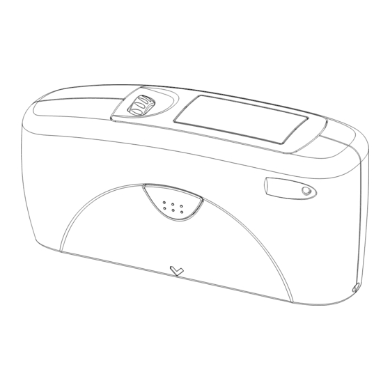
Page 12: Control Elements
Control elements Measurement unit and protective holder Mode scroll wheel: used to turn the unit on and for menu selection Display for user guidance and displaying measurement values Green signal lamp: measurement active; red: error Operate button (measurement button): used to activate measurements Protective holder Calibrating standard... - Page 13 Control elements The basic system consists of the measuring device and the protective holder. The protective holder is used for calibration and to store the measurement unit. Calibration is performed inside the holder automatically at the touch of a button. The gloss standard required for this purpose is kept in the holder and is positioned in such Pressing the operate button starts...
-
Page 14: Getting Started
Getting started Turning on the unit and measuring To turn on the unit, press the mode scroll wheel. Information on the date and last certification appears in the display. If the device was turned on in its holder, the autodiagnosis test is performed (see the section on Calibration). - Page 15 Getting started The measurement values appear in the lower part of the display area. The size of the numbers depends on whether Statistics or Difference measurement has been activated and on the number of geometries displayed. Depending on the measurement mode, a header line also appears for the measurement values.
- Page 16 Getting started You can use the arrow at the top right to switch the display back by one level. Arrows pointing up or down indicate that there are other menu options above or below the part of the menu that is visible. To reach these menu options, simply turn the scroll wheel in the direction in which the arrow is pointing.
- Page 17 Getting started When you enter the name, the arrow jumps to the first character. This allows you to correct any inadvertent incorrect entries. You can confirm the name in these menus at any time with the operate key.
-
Page 18: Overview Of Main Menu
Overview of main menu Mode Sample mode Measurement without statistical evaluation. Statistics Multiple measurement with statistics. Continuous Measurement repetition (measuring interval adjustable). Basic mode Simplest mode: without saving and difference Advanced mode Opens the “Mode” menu again with the previous setting. -
Page 19: Mode And Sample Measurement
Mode and sample measurement You can select from among diffe- rent types of measurement recording and evaluation in the Mode menu. The mode that is activated is identified by a check mark. Single measurements can be performed without statistical evaluation in Sample mode. The results can be saved and compared with a reference. -
Page 20: Statistics
Statistics You can make multiple measurements with each sample in Statistics mode. These measurements will be evaluated statistically and displayed. The results can be saved and compared with a reference. These functions must be previously activated: When Save is turned on, a name is suggested after all measurements of a sample (block). - Page 21 Statistics When the Statistics function is turned on, additional functions are available depending on the context after you press the scroll wheel. Number of measurements You can adjust the number of measurements per sample or per block with this option, from 2 - 99. You can find this value in the measurement display by looking for “n=”...
- Page 22 Statistics Display In the Statistics measurement display, you can assign the following data freely to three columns: Value: Last value to be measured Mean value: Arithmetic mean of the sample (block). Maximum: Highest measurement value of the sample Minimum: Lowest measurement value of the sample Range: The difference between the...
- Page 23 Statistics Std. Dev.: The standard deviation of the sample Difference*: The difference between the sample and a target value. Pass/Fail*: Pass is displayed if the sample value falls within the specified limits, or Fail if it falls outside. Off: Turns off the display of the selected column.
- Page 24 Statistics Exit block This function terminates the block before it reaches the required number of measurements n. It is useful if you have selected a high number of measurements for n, for example in the case of large samples. If Save is turned on, a display appears to enter a block name for the sample.
-
Page 25: Continuous
Continuous You can use this function to perform up to 99 measurements at an adjustable measurement interval. This is helpful when you are covering large samples and you want to evaluate the homogeneity of the surface. If you select this function, you will first be asked to enter the time that defines the interval. -
Page 26: Basic Mode
Basic mode The selection options are limited to the most essential in basic mode. This also greatly simplifies operation in this mode. You can select the geometry and perform calibration. In addition, all functions in the Setup menu item are available. Basic mode is useful if you want to interrupt a series of measurements and quickly perform some other... -
Page 27: Geometry Selection
Geometry selection Geometry selection is only possible with the three angle device. You can select between display of one, two or all three geometries in the measurement display. The currently set angle combination is indicated in the Geometry menu by a check mark. Select the desired combination with the scroll wheel and then confirm by pressing mode. -
Page 28: Save
Save Up to 999 measurements can be stored. To save measurement values, you must activate the Save function before measuring or else select or create an area in memory. A fixed memory area is already created for each geometry or combination (e.g. - Page 29 Save Select memory All available areas of memory are listed in this menu, beginning with the one that is predefined. The number of measurements saved for each area in memory is shown on the right. Select the appropriate memory area with the scroll wheel and activate the selection by pressing mode.
- Page 30 Save Delete memory This menu lists all memory areas that have been created with the number of values stored in each one. Use the scroll wheel to move the mark to the memory area you would like to delete and press the wheel.
- Page 31 Save The values of the first measurement appear in the display. The sample name is displayed in the highlighted field. Turning the wheel switches the display to the next sample with its corresponding values. Which values are displayed in the columns (for example mean value, min., max.) depends on the display currently selected for Statistics.
-
Page 32: 14 Difference Measurement And Pass/Fail
14 Difference measurement and Pass/Fail You can compare the measurement value of a sample with the target value of a saved reference. You can also display whether the test specimen falls within the limits (Pass) or outside (Fail). Up to 50 references can be saved. They are stored in a separate area of memory. - Page 33 Difference measurement and Pass/Fail 14 Measure reference You can use this function to measure a standard to be used as a reference for later measurements. We recommend you perform a number of measurements on the standard with Statistics turned on. Activate “Measure reference”.
- Page 34 14 Difference measurement and Pass/Fail Select reference To select an existing reference, use the arrow to move the mark to Select reference and then press the wheel. The first reference appears in the display. The target value, minimum and maximum are displayed. For values that are not defined, 0.0 or 2000 is displayed.
- Page 35 Difference measurement and Pass/Fail 14 Create reference References can also be saved by entering the limit and target value with the scroll wheel. Move the mark to “Create reference” and activate the function. A display appears in which you must assign a name for the new reference.
- Page 36 14 Difference measurement and Pass/Fail Now you can adjust the corresponding value. After the last number is activated, the display jumps back to the previous menu. In this manner you can enter addi- tional target and/or limit values for the reference one after the other if need be.
- Page 37 Difference measurement and Pass/Fail 14 Delete reference Use the selection wheel to move the mark to Delete reference in the Difference menu and then press the wheel. The Delete reference menu appears. All saved references are listed in this menu. If there are more references than can be shown in the display, arrows on the right edge of the display will...
- Page 38 Calibration and Autodiagnosis Calibration The holder with the integrated glass standard is used for calibration. Always keep the measurement unit in the holder. This protects the measurement optics and ensures that the standard is always at hand. If you have several devices of this type, you must put the unit in the holder which belongs to the unit (see the serial number).
- Page 39 Calibration and Autodiagnosis The autodiagnosis generally takes about 2 seconds. “Please clean standard” or “Please test standard” may be displayed. For more information on cleaning, see page 43. A message will appear in the display informing you that the autodiagnosis has been completed successfully.
- Page 40 Calibration and Autodiagnosis time to allow the optical components to adjust before calibrating and using the unit. You can use the path shown on the left side to reach the Calibrate menu option. To begin calibration, press the scroll wheel. The calibration process is performed automatically for all three geometries.
- Page 41 Calibration and Autodiagnosis Scale You can use the Scale menu option to switch back and forth between Gloss Units and Reflectance (see the Section on Practical measuring suggestions). Move the mark to the desired entry and press mode. A check mark identifies the Scale that is selected.
- Page 42 Calibration and Autodiagnosis In some cases, a selection menu may appear for geometries. Select the desired geometry and press the scroll wheel. A warning message appears. You can cancel this process by pressing the operate button. If you press the scroll wheel, you will continue with the process of changing calibration values.
-
Page 43: Calibration And Autodiagnosis
Calibration and Autodiagnosis Calibrating standards If cleaning and recalibration do not offer any improvement, please get To ensure exact calibration, only in touch with our Customer Service. original standards from the Cleaning standards manufacturer should be used. These are calibrated against tested The accuracy of the measurement primary standards. -
Page 44: Setup
Setup You can make general settings in the Setup menu, for example Language or Display time. Date/Time The unit contains an integrated clock. This makes the date and time of the measurement available for data transfer to a PC. The date and time are not lost even when the battery is changed. - Page 45 Setup Display time To save electricity, the unit automatically turns off after a certain amount of time. You can determine this time yourself with Display time. Language You can use this menu to select the display language. Use the scroll wheel to move the mark to the desired language and press the wheel.
- Page 46 Practical measuring suggestions In accordance with the standard, Paints and varnishes, plastics the reflectometer value is related to and similar materials a black glass standard at a defined index of refraction (generally 1.567) The various geometries are which is thus equal to 100 units. distinguished according to their fields of application as follows: Reflectometers are differentiated by...
-
Page 47: Practical Measuring Suggestions
Practical measuring suggestions Anodized aluminum and other Notes metal surfaces Proper measurements are only The measuring unit is equipped possible on level surfaces. with an extended measuring range Measurements on dirty, scratched for measuring samples with a very or otherwise distorted areas of the high reflectance. -
Page 48: Standards
Standards DIN 67 530 The reflectometer as an aid in evaluating gloss on level paint and plastic surfaces (Reflektometer als Hilfsmittel zur Glanzbeurteilung an ebenen Anstrich - und Kunststoffoberflächen). ISO 2813 Paints and varnishes - Measurement of specular gloss of non-metallic paint films at 20°, 60°... -
Page 49: Interface
Interface The measurement device is equipped with a serial interface that allows for direct communication with a PC. Measurement data can be transfer- red from memory or directly after each measurement. The easy-link program is included with delivery for this purpose. Your transferred data is displayed immediately in a test report. -
Page 50: Technical Data
Technical data Measurement geometry 20° 60° 85° Size of measurement spot (mm) 10 x 10 9 x 15 5 x 38 Color sensitivity in spectral adjustment to CIE luminosity function (2°) under CIE illuminat C Memory 999 measurements with date and time, in up to 50 memory areas Difference measurement Memory for 50 references... -
Page 51: Delivery Notes
Reflectometer according to DIN, ISO, ASTM micro-gloss 20° 4420 micro-gloss 60° 4460 micro-gloss 85° 4485 micro-TRI-gloss 4430 Comes complete with: Measurement device, holder with integrated calibration standard, tracable certificate, easy-link software, PC cable, operating instructions, battery, carrying case. Checking standards Test standard 20°...
Need help?
Do you have a question about the micro-TRI-gloss and is the answer not in the manual?
Questions and answers