
Subscribe to Our Youtube Channel
Related Manuals for BYK CAP 1000+


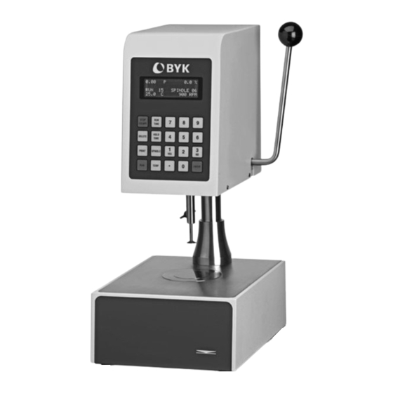
Summary of Contents for BYK CAP 1000+
- Page 1 Measure what you see. CAP 1000+ Viscometer Manual A member of Additives & Instruments...
- Page 3 CAP 1000+ Viscometer Manual 199 024 584 E 1610 BYK - Gardner USA BYK-Gardner GmbH 9104 Guilford Road Lausitzer Str. 8 Columbia, MD 21046 D-82538 Geretsried Germany Phone 800-343-7721 Tel. 0-800-gardner 301-483-6500 (0-800-4273637) 800-394-8215 +49-8171-3493-0 301-483-6555 +49-8171-3493-140 www.byk.com/instruments...
- Page 4 - Technical & Application Support - Application and Technical Seminars - Repair & Certification Service BYK-Gardner is part of the Additives and Instrument Division of ALTANA AG, a leading supplier of additives for coatings and plastics. Together, we offer complete and unique solutions for you our customer. Thank you for your trust and confidence. If there is anything we can do better to serve your needs, do not hesitate to let us know.
-
Page 5: Table Of Contents
Table of Contents TABLE OF CONTENTS I. INTRODUCTION ....................7 I.1 Components ......................8 I.2 Utilities ........................9 I.3 Specifications ......................9 I.4 Installation ......................10 I.5 Safety Symbols and Precautions ................. 11 I.6 Key Functions ....................... 12 I.7 Viscosity and Temperature Display ..............13 I.8 Cleaning ....................... -
Page 7: Introduction
Introduction I. INTRODUCTION The CAP Series Viscometers are Cone and Plate geometry high shear rate instruments with integrated temperature control of the test sample material. The CAP 1000+ is a fixed shear rate viscometer rotating at 750 RPM and 900 RPM. The instruments operate by digital setting and display; rotational speed can be automatically timed to stop. High shear rate viscosity measurements are made over various viscosity ranges depending upon the cone spindle and the rotational speed (shear rate). -
Page 8: Components
See Table A-1 in Appendix A Please check to be sure that you have received all components, and that there is no damage. If you are missing any parts, please notify BYK-Gardner or your local BYK-Gardner representative immediately. Any shipping damage must be reported to the carrier. -
Page 9: Utilities
This symbol indicates that this product is to be recycled at an appropriate collection center. Users within the European Union: Please contact your dealer or the local authorities in charge of waste management on how to dispose of this product properly. All BYK- Gardner offices and our network of representatives and dealers can be found on our website: www.byk.com Users outside of the European Union: Please dispose of this product according to your local laws. -
Page 10: Installation
Installation I.4 INSTALLATION NOTE: DO NOT lift the viscometer by the handle or display panel! LIFT by the base console or column! 1) Set the viscometer on a clean level bench surface. 2) Remove shipping spindle blank and foam packing from CAP Viscometer. Store the spindle blank in the spindle case. -
Page 11: Safety Symbols And Precautions
Safety Symbols and Precautions I.5 SAFETY SYMBOLS AND PRECAUTIONS SAFETY SYMBOLS The following explains safety symbols which may be found in this operating manual. Indicates hazardous voltages may be present. Caution: HOT surface. Refer to the manual for specific warning or caution information to avoid personal injury or damage to the instrument. SAFETY OVERVIEW If this instrument is used in a manner not specified by the manufacturer, the protection provided by the instrument may be impaired. -
Page 12: Key Functions
Key Functions I.6 KEY FUNCTIONS Figure I-1 shows the control keys on the face of the viscometer display panel: NUMERIC 0-9 Used for data entry ENTER Accepts entered data STOP/ESCAPE Stops cone spindle rotation at any time / Exits data entry field DELETE Overwrites entered data PRINT Sends data to the parallel port Starts spindle rotation and measurement RUN TIME Selects time entry mode (time of spindle rotation) -
Page 13: Viscosity And Temperature Display
Viscosity is displayed in either P=Poise or cP=Centipoise (CGS system) or Pa•s=Pascal seconds or mPa•s=milliPascal seconds (SI system). If the viscosity measurement is over range, “EEEE” will be displayed. BYK-Gardner recommends a minimum reading of 10%. If the display value is between 0 and 10%, the unit display will flash to indicate an out of range condition. If the viscometer settles out with a... -
Page 14: Getting Started
II.1 POWER ON Turn the power ON using the switch located on the rear of the base console. The display will sequentially show BYK-GARDNER, then the model of the viscometer and the version number. After about four seconds, the main screen will be displayed (Figure II-1), indicating the temperature of the sample plate. - Page 15 Cone Spindle Selection and Setting Thumb Screw Figure II-2 Solvent Trap Cone Spindle Viscometer in measurement position Viscometer in „cleaning“ position When using the solvent trap, connect it to the cone adapter by sliding it up, passing the slot by the thumb screw and turning the trap clockwise onto the thumbscrew.
-
Page 16: Ii.3 Speed Setting
It is recommended to have the spindle in contact with the plate prior to introducing the sample material to ensure that the spindle is also at the temperature of test. BYK-Gardner recommends using the solvent trap at all times to enhance the temperature control of the sample material. -
Page 17: Ii.5 Hold Time Settings
Hold Time Settings / Run Time / Printing II.5 HOLD TIME SETTINGS Hold time sets the time period between when the RUN key is pressed and when the spindle begins to rotate. This time period is normally used to ensure thermal equilibrium of the sample and spindle. -
Page 18: Ii.8 Run And Stop Keys
Run and Stop Keys II.8 RUN AND STOP KEYS The RUN key has three functions: 1. Press RUN to execute a timed measurement. 2. Press and hold the RUN key for continuous rotation when 00 is the timer setting. 3. Used in executing a cone calibration. The STOP key has three functions: 1. -
Page 19: Operation
CAP Viscometers is the indicated percentage of the full scale range. See Appendix A for information on how to determine Full Scale Viscosity Range (FSR). Please contact BYK-Gardner for accuracy information for CAP spindles 07-10. Table III-1 Accuracy of Viscosity Measurement CAP 1000+L VISCOMETERS... -
Page 20: Iii.2 Repeatability
However, more weight means more wear on the cone and plate. Additional weights should only be considered when definitely required and removed when not required. Contact BYK-Gardner or your local BYK-Gardner Representative for details on the above information. III.3 MAKING VISCOSITY MEASUREMENTS The following procedure is recommended for making a viscosity measurement. - Page 21 NOTES: 1. Lock the cone tightly into the adapter. 2. When measuring volatile samples such as paints and coatings, and when using either a high temperature CAP 1000+H or CAP 2000+H, the solvent trap must be put in place over the cone to prevent the test sample from drying out during the rotation of the cone.
- Page 22 Making Viscosity Measurements Read the results of the sample test on the printer or write down the test conditions and viscosity results from the viscometer display. 10. Relocate the solvent trap onto the cone adapter and raise the handle. 11. It is recommended to remove the cone for cleaning. However, with care, the cone can be cleaned in place.
-
Page 23: Appendix A - Cone Numbers, Sample Sizes, Viscosity Ranges
Appendix A APPENDIX A - CONE NUMBERS, SAMPLE SIZES, VISCOSITY RANGES CAP 1000 AND 2000 VISCOMETERS Calibrating Fluid Calibrating Fluid Cone Shear Rate Sample Size Low Temp Cap at 25°C High Temp Cap at 60°C Number (sec (micro liters) Part No. *Viscosity Part No. - Page 24 Appendix A SAMPLE SIZE It is necessary that sufficient sample is placed between the cone and plate to completely cover the surface of the cone when the cone is locked in the RUN position. With sufficient sample, an excess of about 1 mm in width will be seen around the periphery of the cone edge. For calibration and best reproducibility of results, the sample sizes shown in Table A1 should be used.
- Page 25 Appendix A EXAMPLE: CAP 1000+L Viscometer; Cone (02); running at 750 RPM; temperature 25.0°C; % FSR = 73.8. Determine the viscosity (poise), shear stress (dynes/cm2), shear rate (sec-1). Using Equation A2, determine the full scale viscosity range at 750 RPM: 3,750 Full Scale Viscosity Range (poise) = = 5.00 poise Using Equation A5, determine the viscosity at 73.8% of full scale range: 73.8...
-
Page 26: Appendix B - Calibration Procedures
When verifying the calibration of the CAP 1000+, the instrument and viscosity standard fluid error must be combined to calculate the total allowable error. The CAP 1000+ accuracy is defined in Section III.1 as a function of spindle number 03. BYK-Gardner Viscosity Standards Fluids are accurate to (+/-) 1% of their stated value. EXAMPLE: Calculate the acceptable range of viscosity using CAP 1000+ with Spindle 03 at 900 RPM; Standard Fluid CAP-3L with a viscosity of 350 cP at 25°C:... - Page 27 Appendix B CONE CALIBRATION A special feature of the CAP Series Viscometers allows the user to perform a cone calibration using Viscosity Standard Fluids. This field calibration will accommodate any wear on the tip of the cone which may result from contact with the plate. NOTE: A cone calibration should be performed when: 1) using a new cone for the first time, 2) switching between two cones of the same number and 3) verification of calibration provides data outside of the acceptable range.
- Page 28 CUSTOM SPINDLES The CAP Series Viscometer allows for the use of custom spindles. Please contact BYK-Gardner’s Technical Sales Department for more information. Custom spindles are calibrated using spindle entry codes 11-20. The calibration of a custom spindle requires the entry of two parameters: SMC and SRC. The SMC and SRC are required for proper calculation of viscosity.
-
Page 29: Appendix C - Variables In Viscosity Measurement
Appendix C APPENDIX C - VARIABLES IN VISCOSITY MEASUREMENTS As with any instrument measurement, there are variables that can affect a Viscometer measurement. These variables may be related to the instrument (Viscometer), or the test fluid. Variables related to the test fluid deal with the rheological properties of the fluid, while instrument variables would include the Viscometer design and the spindle geometry system utilized. RHEOLOGICAL PROPERTIES Fluids have different rheological characteristics that can be described by Viscometer measurements. We can then work with these fluids to suit our lab or process... - Page 30 Appendix C VISCOMETER RELATED VARIABLES • Most fluid viscosities are found to be non-Newtonian. They are dependent on Shear Rate and the spindle geometry conditions. The specifications of the Viscometer cone and plate geometry will affect the viscosity readings. If one reading is taken at 400 rpm, and a second at 1,000 rpm, the two viscosity values produced may be different because the readings were made at different shear rates.
-
Page 31: Appendix D - Warranty Repair And Service
Appendix D APPENDIX D – WARRANTY REPAIR AND SERVICE WARRANTY BYK-Gardner Viscometers are guaranteed for one year form the date of purchase against defects in materials and workmanship. They are certified against primary viscosity standards traceable to the National Institute of Standards and Technology (NIST). The Viscometer must be returned to BYK-Gardner USA or the BYK-Gardner dealer from whom it was purchased for warranty service. - Page 32 199 024 584 E 1610...
Need help?
Do you have a question about the CAP 1000+ and is the answer not in the manual?
Questions and answers