
Related Manuals for RADWAG AS R2.PLUS


Summary of Contents for RADWAG AS R2.PLUS
- Page 1 R Series Balances AS R2.PLUS Analytical Balances PS R1 Precision Balances PS R2 Precision Balances PS R2.H Precision Balances USER MANUAL IMMU-03-39-02-20-EN www.radwag.com...
- Page 2 If you are reading this, it means that you are bound to achieve success. You have purchased a device that was designed and manufactured to give you years of service. Congratulations and thank you for selecting RADWAG product. FEBRUARY 2020...
-
Page 3: Table Of Contents
TABLE OF CONTENTS General Information ..................6 1.1. Dimensions ..................6 1.2. Connectors ................... 7 1.3. Connection Cables - Diagrams ..............7 1.4. PS R2.H Series ..................7 1.5. Intended Use ..................9 1.6. Inappropriate Use ................. 9 1.7. Warranty ..................... 9 1.8. - Page 4 8.3. Non-standard Printouts ................ 28 8.3.1. Inserting Text ..................28 8.4. Variables ................... 30 Databases ....................30 9.1. Users ....................30 9.2. Products .................... 31 9.3. Tares ....................32 9.4. Weighings ..................32 9.5. ALIBI Memory ..................33 10. Export and Import of Databases ............... 34 10.1.
- Page 5 11.11.1. Additional settings ................62 11.11.2. Means of Operation ................62 11.12. Peak Hold ..................64 11.12.1. Means of Operation ................64 11.13. Adding ..................65 11.13.1. Means of Operation ................65 11.14. Pipettes Calibration ................. 67 11.14.1. Additional settings of pipettes calibration mode ........67 11.14.2.
-
Page 6: General Information
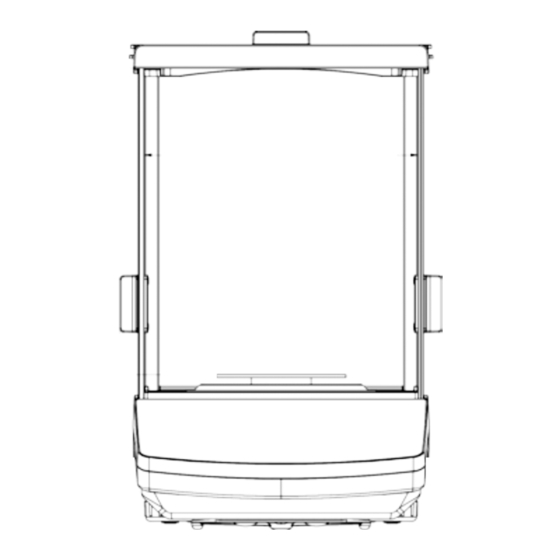
1. GENERAL INFORMATION 1.1. DIMENSIONS AS PLUS series: PS 200/2000 - PS 1000 PS 2100 - PS 10100 - 6 -... -
Page 7: Connectors
1.2. CONNECTORS Power supply socket COM 2 connector (additional display or external buttons) COM 1 connector (printer) USB 2, type B (computer) USB 1, type A (keyboard) 1.3. CONNECTION CABLES - DIAGRAMS Scale – computer cable (RS232) Scale – printer cable (CITIZEN, EPSON) 1.4. - Page 8 Balance with pan Φ 115 mm Balance with pan 195x195 mm Balance assembly Upon unpacking the balance remove any protective elements assembly balance: Install: • metal weighing pan (2) draft shield (1), for balances with pan Φ • 115 mm •...
-
Page 9: Intended Use
1.5. INTENDED USE X2 series balances are designed to provide accurate measurement of weighed loads, performed under laboratory conditions. It is intended for application as a non-automatic weighing instrument only, i.e. the material to be weighed is manually and carefully placed in the centre of the weighing pan. -
Page 10: Package
2.2. PACKAGE Keep all package elements should your device be transported in a future. Remember that only original packaging can be used for shipping purposes. Prior packing uncouple any cables, remove any separable components (weighing pan, shields, inserts). The device components shall be packed into an original packaging, thus being protected against potential damage during transportation 3. - Page 11 AS R2.PLUS • remove a transport lock (1) – gently press the transport lock and turn it accordingly to <OPEN> instruction, keep the transport lock should your balance be transported in the future. • Install components following the above diagram: •...
-
Page 12: Settings
3.4. SETTINGS It is necessary to level the balance prior connecting it to the mains. To level the balance turn its feet until an air bubble takes the central position. The balance shall rest on a surface firmly, each of the feet must be supported. 3.5. - Page 13 While polishing the surface use circular movements. Use clean, dry cloth. In order to ease cleaning of glass draft shield panes, it is permissible to remove them following the below instruction. AS R2.PLUS series balances; disassembly steps: Detach the front part Detach the back...
-
Page 14: Powering The Device
Remove back Remove left pane of the chamber. and the right side pane. Carefully disassembly the weighing pan, the draft shield and the bottom insert. Clean the weighing chamber and the panes. All the operations have to be done carefully. Pay special attention to the spot where the weighing pan is installed;... -
Page 15: Connecting Additional Hardware
3.7. CONNECTING ADDITIONAL HARDWARE Use only accessories and peripheral equipment recommended by the manufacturer. The balance must be disconnected from the mains before connecting or disconnecting any peripherals (printer, PC computer, computer keyboard). On connecting the peripherals, plug the balance to the mains. 3.8. -
Page 16: Start-Up
5. START-UP When plugged to mains, the balance displays program name and number, next it proceeds to the weighing mode. 5.1. TEMPERATURE STABILIZATION PERIOD Before start of measuring processes, it is necessary to wait until the balance reaches thermal stabilisation. For balances that were stored in much lower temperatures before plugging to mains (e.g. - Page 17 DOSING [settings for the function dosing] P2.5 DEVIATIONS P2.6 [settings for the function deviations % against the mass of the standard] DENS. OF SOLIDS [settings for determining density of solids] P2.7 DENS OF LIQUIDS [settings for determining density of liquids] P2.8 P2.9 ANIMAL WEIGHING...
-
Page 18: Logging
P8 UNITS ACCESSIBILITY [declaration of units to be available for balance P8.1 operation] START UNIT [selection of a start unit, unit active on balance start- P8.2 USER UNIT U1 [parameter defining user’s unit 1] P8.3 USER UNIT U2 [parameter defining user’s unit 2] P8.4 P9 IMPORT/EXPORT (parameter displayed upon inserting the USB flash drive to the balance) EKSPORT... -
Page 19: Temporary Measuring Unit
5.6. TEMPORARY MEASURING UNIT Function enables selecting a measuring unit which is to be indicated next to mass reading during the operation. The set measuring unit will be in use from the moment of its activation until its change or switching the balance off and on. -
Page 20: Custom Unit
5.9. CUSTOM UNIT You can declare two custom units. The custom unit is a result of indication multiplied by a specified coefficient. The units are displayed as [u1] – user unit 1, and [u2] – user unit 2. Procedure for declaration of coefficient for the custom unit: Custom units are valid for verified balances exclusively. - Page 21 Backlight turn-off time Parameter <P6.5 STAND-BY MODE> enables use of function responsible for activation of the display stand-by mode when weighing process is not being performed (stable indication is a necessary condition for activation of the stand-by mode). NONE – backlit turn-off time not activated 0.5;...
- Page 22 main purpose of the function is the possibility of monitoring the above-mentioned parameters at optional moment and saving records from the carried out tests in the form of printed reports of the tests that are automatically generated at the end of examination. The test controls repeatability of placing the interval weight and determining error of indication with reference to balance’s maximum capacity.
-
Page 23: Adjustment
7. ADJUSTMENT In order to ensure the highest weighing accuracy, it is recommended to periodically introduce a corrective factor of indications to balance memory, the said factor must be referred to a mass standard. In other words, balance adjustment shall be performed from time to time. Adjustment should be carried out: •... -
Page 24: Adjustment Menu Settings
• Adjustment triggered by elapsing time. You can declare time intervals which are criteria for balance adjustment (this option is only available for non-verified balances). 7.2. ADJUSTMENT MENU SETTINGS • P1.1 INT. CALIB. – Internal adjustment Start of an internal adjustment process. Adjustment is conducted automatically, and no user assistance is required. -
Page 25: External Adjustment
process is aborted, balance returns to the weighing mode. Adjustment process may be repeated upon removal of the excess load. 7.3.2. External Adjustment The external adjustment for PS series balances should be carried out with an external mass standard of class F (function unavailable for verified balances). -
Page 26: Header, Footer, Glp Printouts
Variable Overview PROJECT Option enables naming the project (name associated with a particular type of weighing). The name may consist of 16 characters maximum. CALIB TYPE Option enables printing out the type of the adjustment being carried out. USER Option enables printing out the name of a logged-in user. PROJECT Option enables printing out the name of the project (see parameter Project). - Page 27 Option enables printing out the time of the carried out Header TIME adjustment. GLP printout Footer Option enables printing out the value of VARIABLE 1. Header VARIABLE 1 GLP printout Footer VARIABLE 2 Option enables printing out the value of VARIABLE 2. Header GLP printout Footer...
-
Page 28: Non-Standard Printouts
8.3. NON-STANDARD PRINTOUTS The balance software enables entering 4 non-standard printouts. Each of them can consist of approximately 160 characters. Non-standard printout may include: • variables dependent on the working mode and other needs (mass, date etc.) • permanent text from the user menu, remember to use capital letters exclusively, no Polish signs allowed •... - Page 29 Example 1: “RADWAG” DATE: <current measurement date> TIME: <current measurement time> PRODUCT MASS: <current mass indication> *****SIGNATURE:..<current working mode> Enter printout content settings and design the printout using respective data variables and characters for text format. Example 2: To crop the paper after the printout had been carried out by EPSON printer (if the printer is equipped with an autocutter blade) the user must select (for a given printout: HEADER, GLP PRINTOUT or FOOTER) an option of non-standard printout 1,2,3 or 4 with <%E>...
-
Page 30: Variables
8.4. VARIABLES Variable is defined as alphanumeric data which can be linked to printouts, products or other information related to weighing. Every variable is characterized by its content, the content must be given. Variables are used for entering various data during the weighing process, e.g. serial number or batch number. -
Page 31: Products
Once the user name is added, enter the following: User code – Max 6 characters, User password – Max 8 numbers. Next select: • Access level (USER, ADV, ADMIN) • Language In order to remove a user you should follow this procedure: •... -
Page 32: Tares
9.3. TARES TARES – 10 different weights of the packaging. The following data can be inserted for each packaging: • NAME (30 characters), • TARE (packaging weight, enter a value with the accuracy of a reading unit). In order to add tare – packaging weight, enter tare database and add name of the tare along with respective data (follow the procedure as in Users section). -
Page 33: Alibi Memory
To view the remaining data relating to a respective measurement, first select the measurement in question, next press button: The software automatically shows the data relating to the measurement, data is presented in the bottom line of the balance display. To swap between data relating to the measurement, press . -
Page 34: Export And Import Of Databases
• Person carrying out the measurement (logged-in user) • The name of the product that has been weighed The software saves the measurements in a so called loop, i.e. when the measurement 100 001 is saved, the measurement 1 is automatically deleted from the balance’s memory. The measurements saved in the balance’s memory cannot be deleted. -
Page 35: Database Esport
Special computer software manufactured by RADWAG company is used to read data from database files: ALIBI and WEIGHINGS. The data from files storing information from PRODUCTS, USERS, and TARES databases is read automatically by the balance software when option <IMPORT>... -
Page 36: Measurement Data Printout
10.3. MEASUREMENT DATA PRINTOUT Balance software allows the user to save data, relating to a measurement, on an external USB flash drive. The operation can be performed as follows: • Plug a flash drive into USB port. • Press button to abandon automatically started <IMPORT/EXPORT> option. •... -
Page 37: Working Modes Accessibility
Once the button has been pressed, the name of the first available function is shown. - press to select working mode - press to enter the selected working mode CAUTION! Upon restart, the balance is launched with the most recently operated working mode!!! For settings of this function read later sections of this user manual. -
Page 38: Weighing Operation
11.2. WEIGHING OPERATION 11.2.1. Good Weighing Practice In order to ensure long lasting use of a balance plus correct and reliable measurement of weighed loads, follow below procedures: • Start the balance with no load on the weighing pan (permissible value of load on the weighing pan on balance start is ±10% of its maximum capacity). -
Page 39: Balance Zeroing
11.2.2. Balance Zeroing Zeroing is a function allowing to zero mass indication. In order to zero mass indication, press button. Mass indication of zero value shall be displayed together with precise zero and stability markers. Zeroing process is an equivalent for determining new zero point, recognized by the balance as precise zero. -
Page 40: Weighing Profiles
• Use the arrow buttons to select the tare which is to be recalled and press button. • The balance returns to the weighing mode, and the display indicates entered tare value with a minus „–" sign. Deleting tare Entered tare value can be deleted by pressing button on the overlay or by entering tare value of 0.000g (see description above). -
Page 41: Weighing Mode Settings - Readout
11.2.5. WEIGHING Mode Settings - Readout The software allows setup of operating parameters (filters, value release and autozero function, deleting the last digit and other settings) separately for each working mode. Only for User profile you can modify all settings. For other profiles (Fast, Fast dosing, Precision) Filter and Value release parameters are default and cannot be modified. -
Page 42: Autotare
indication is close to zero. If results vary less than the declared AUTOZERO range e.g. one division, balance zeroes automatically, marker of stable measurement result – , and precise zero marker – are displayed. If AUTOZERO function is enabled, then each weighing process starts from precise zero point. There are, however, some cases when this function can be a disturbing factor for the measuring process;... -
Page 43: Print Mode
• Put a next product that is to be packed. For correct operation of the balance with AUTOTARE function, it is necessary to adjust the threshold value. <AUTO THRES> parameter is connected with the following functions: • automatic tare, • automatic operation, No automatic taring takes place as long as the gross weight value stays within the range set in <AUTO THRES>... -
Page 44: Information
• The next measurement is possible when the indication is lower than the set value of <AUTO THRES.> parameter (next measurement does not require zero value). Procedure: For automatic operation adjust the threshold value. 11.2.8. Information Function enables displaying additional information in the bottom line. Depending on the needs, you can choose the following options, which are shown while working in <WEIGHING>... -
Page 45: Non-Standard Information
<BARGRAF> option presents amount of used weighing capacity in a graphic form, it covers 0 – MAX range. Example of a PS 1000.R2 balance display with bargraph option on: 500 g heavy load placed on a weighing pan means that 50% of max capacity has been used (half-filled bargraph bottom line). It is possible to enable <BARGRAF>... - Page 46 Functions for particular working modes: Function Modes featuring the function SELECT PRODUCT All modes LOG IN All modes ENTER TARE All modes SELECT TARE All modes PRINT HEADER All modes PRINT FOOTER All modes VARIABLE 1 All modes VARIABLE 2 All modes ON/OFF LAST DIGIT All modes...
-
Page 47: Dual Range Balance (Ps 200/2000.R2)
In standard analytical and precision balances, loads can be weighed under a weighing pan. Such means of operation requires placing a balance in an uplifted position. RADWAG offers a rack for under-pan weighing. The rack is an optional equipment offered for PS series balances. -
Page 48: Counting Parts Of The Same Mass
CAUTION! The suspension for hook must not be turned, twisted or manipulated in any direction. Such actions may cause damage to balance mechanism. Mass of all additional elements of under pan weighing kit, like the hook, weighing pan, string, etc. should be zeroed by pressing 11.3. -
Page 49: Setting The Reference Mass: Entering Mass Value
• Use arrow buttons to select the correct sample quantity. • For optional quantity variable (displayed value <0000>) enter any number using arrow buttons • Confirm selected sample quantity, confirmation message - <PLACExx PCS> - shall be seen. • Place the declared number of pieces in the container and when the result is stable (the symbol is displayed) confirm the mass by pressing button, •... -
Page 50: Checkweighing
• The balance software automatically enters <PARTS COUNTING> mode displaying the number of pieces which are on the pan (pcs). In the bottom line, a single piece mass value is shown (if the option has been selected for <INFORMATION> function) 11.4. -
Page 51: Dosing
<Ok>: mass contained within thresholds <Max>: mass higher than the value of the high threshold Since LCD display capacity is limited, the threshold markers do not reflect threshold setups and target weight value precisely. They provide rough information and serve as user aid in course of the balance operation. -
Page 52: Percent Weighing Control With Relation To Reference Mass
• The sign <Min> is shown at the top of the display. It indicates the status of the mass on the pan with relations to the target mass. Bottom line of the display, if <BARGRAPH> option is enabled, shall demonstrate weight indication, in a graphic form, in relation to target weight and set tolerance value <Min>: mass lower than the Target Value - Tolerance <Ok>: mass contained within tolerance Target Value +/- Tolerance... -
Page 53: Setting The Reference Mass: Entering Mass Value
11.6.2. Setting the Reference Mass: Entering Mass Value Procedure: • Press F button to which function <ENTER SAMPLE> is assigned, <ENTER SAMPLE> editing window is displayed. • Use arrow buttons to enter the known reference mass value, press button to confirm. •... -
Page 54: Running The Process Manually - Means Of Operation
F Shortcut Keys You can declare which particular weighing function is to be launched using F1, F2, F3 or F4 keys. For procedure informing you how to declare the particular function, read F Shortcut Keys section. 11.7.2. Running the Process Manually – Means of Operation To start the process of weighing manually, enter the mode settings, select an <AUTOSTART>... -
Page 55: Running The Process Automatically - Means Of Operation
After weighing process completion, the measurement result is locked and automatically printed. In order to finish the measurement, press button. The program automatically returns to the main window of Animal weighing mode. 11.7.3. Running the Process Automatically – Means of Operation To start the process of weighing automatically, enter the mode settings, select an <AUTOSTART>... - Page 56 Flexible connector Sinker Top weighing pan for solids Beaker basis density determination Beaker Additional stand for a set of pans or a sinker Additional weighing pans density Hanger determination of solids with density lower that density of water Kit intended for AS balances. Beaker base Hanger Stand...
-
Page 57: Density Determination
F Shortcut Keys You can declare which particular weighing function is to be launched using F1, F2, F3 or F4 keys. For procedure informing you how to declare the particular function, read F Shortcut Keys section. 11.8.1. Density Determination Density determination of solids can be carried out by means of two pre-defined types of liquids or user-defined liquid of specified density: •... -
Page 58: Density Of Liquids
13. Next, place a mass sample on the bottom pan of the kit (mass determination in the liquid), and confirm the indication when stable. 14. On the second confirmation of the indication, the program automatically calculates and displays the tested solid object density. At the same time, a report on the measurement is sent to a selected port of a printer. -
Page 59: Density Determination
Settings for button shortcuts are the same as for <SOLIDS DENSITY> function (see the previous point). 11.9.1. Density Determination The basic element for measuring liquids density is the sinker (9). Its volume is precisely determined and given on a sinker’s hanger. Before starting liquid density determination, enter sinker’s volume value to the balance memory. -
Page 60: Statistics
An exemplary report: The report may be reprinted upon pressing button. In order to finish, press button. The software returns to the main window of the mode and a next measurement can be performed. The balance operates with previously set parameter values (liquid, temperature) thus shortening time needed for the exact measurement. -
Page 61: Deleting Statistics
• When all the measurements are saved, it is possible to check the results of statistics by pressing button: • Select an option <RESULT> by pressing button. • The information on number of saved measurements is displayed in a bottom line. On pressing , the type of displayed information changes. -
Page 62: Totalising
Activating <FINISH> option results in printing out the statistics data and moving to a <RESULT> window, using this window it is possible to check the data and print it out again, if necessary. To exit, press button. This leads to returning to the main window of <STATISTICS> mode and zeroing the data related to carried out measurements. - Page 63 The software adds mass of the ingredient to the total mass, next automatic taring of the indication proceeds (zero indication is shown on the main display). In the bottom line modified data relating to the number of ingredients and total sum is presented. •...
-
Page 64: Peak Hold
It is possible to print out the report again by pressing button. To exit this window, press button. The main window for <TOTALISING> mode is displayed, data related to carried out measurements is automatically zeroed. 11.12. PEAK HOLD This function enables snapping peak hold applied to the weighing pan during a single checkweighing process. -
Page 65: Adding
11.13. ADDING Adding function allows you to add net masses of weighed samples. This function enables adding maximum 9999 ingredients in one cycle or such quantity of samples which value of totalized masses is possible to be displayed on 8-section display. F Shortcut Keys Function enables assigning quick access functions which are to be accessible by pressing F1, F2, F3 or F4 keys. - Page 66 In the bottom line message <RESULT> is displayed. It means that the total result of all measured samples masses is displayed and the sum is automatically printed. An exemplary printout: CAUTION: On adding process completion, only a summary is printed. Masses of particular samples are printed on confirmation.
-
Page 67: Pipettes Calibration
CAUTION: for ADDING mode, on pressing button (confirming mass of measured sample) data connected with the measurement is printed. The following data can be printed: Measurement number, NET mass (in calibration unit), TARE mass (in current unit), GROSS mass (in current unit), and current result (in current unit). -
Page 68: Means Of Operation
Additional settings list: • VOLUME DETERMINATION – allows to predefine number of tested volumes for a particular pipette. For pipettes with fixed volume please set parameter <1>, for pipettes with adjustable volume set parameter <2> and <3>. • MEASUR. NO – allows to predefine number of measurements for each tested volume. Number of measurements ranges from 6 to 20. - Page 69 • Enter (V2) control volume. The computer software proceeds to the next step, i.e. entering the third control volume (V3) for a tested pipette. • Enter (V3) control volume. • Upon entering the data the computer software proceeds to pipettes calibration. •...
-
Page 70: Communication
12. COMMUNICATION Communication menu enables configuration of port settings. The settings are accessed upon pressing button. Communication with peripheral devices is established via the following ports: • COM 1 (RS232), • COM 2 (RS232), • USB type A • USB type B •... -
Page 71: Rs 232 Ports Settings (Com)
12.1. RS 232 PORTS SETTINGS (COM) Procedure: • Select communication port <COM 1> or <COM 2>, • Set respective values The RS 232 ports enable the following setting of transmission parameters: • Baud rate – 2400, 4800, 9600, 19200, 38400, 57600, 115200 bit/s •... -
Page 72: Port Usb
Ensure that the settings are correctly entered, and repeat the connecting process. If this fails, contact your RADWAG service representative. Selected network and parameters settings are stored by the balance memory, each time when the balance is launched the software connects to the network referring to the set parameters. - Page 73 To carry out this procedure, the user needs a respective driver installer which may be either downloaded from www.radwag.com website or taken from a CD with manuals: R X2 SERIES RADWAG USB DRIVER x.x.x.exe. Steps: Run driver installer Startup dialog window: Select language version.
- Page 74 Having completed driver installation, connect balance to a computer, use 1,8-meter long USB A/B cable maximally (in case of already connected balance, it is necessary to disconnect it and using USB cable connect the balance again). The system detects the new USB device and automatically starts searching a respective driver Go to Device Manager and check number assigned to virtual COM port.
-
Page 75: Peripheral Devices
• communication with a balance, • switching the continuous transmission on and off, and • cooperation of a balance with E2R software of Radwag production. 13.1.1. Computer Connection Port Procedure: press button enter <P4 DEVICES> menu enter menu group: <P4.1 COMPUTER>... -
Page 76: Continuous Transmission
– value ‘NO’ – cooperation with other programs (mass value transferred in a form of text), DELAY – if the transferred information is incomplete, i.e. part of it gets lost (due to auto- entering or auto-formatting of data by computer program) during cooperation with Excel type program, set the parameter value to <2>. -
Page 77: Printouts Interval For Continuous Transmission
USB 1 type A – USB port, for connecting a PCL printer or EPSON printer WIFI – WIFI port for transferring data from balance to a dedicated RADWAG software (e.g. PW WIN operated on a computer connected to balance via wireless communication). - Page 78 *.csv (,) format (file that can be opened using Excel, the transferred decimal value is separated using coma character) USB PC – USB port type B, for connecting a computer with a dedicated RADWAG software, e.g. PW WIN. USB FREE LINK – USB port, type B, for connecting a computer. Tool for entering data, it functions as a keyboard.
- Page 79 This function is most frequently used to send an information about the code page of a printout sent by a balance, at the beginning, and to send a command enabling the crop of a paper in EPSON printers (if the printer is equipped with an autocutter blade), at the end. <PREFIX>...
-
Page 80: Barcode Reader
• select port to which the barcode reader is to be connected: NONE, COM 1, COM 2 CAUTION! R series balances are compatible with RADWAG barcode scanners 13.4. ADDITIONAL DISPLAY Submenu <ADDITIONAL DISP.> comprises settings for cooperation with WD-6 external additional display. -
Page 81: Cooperation With Peripherals
buttons, first connect a several electrical outlet to COM 2 port, next connect buttons TARE and PRINT to the electrical outlet. Connect the printer or terminal to COM 1 or to the electrical outlet (determine the PRINTER- BALANCE transfer perameters). Every time the user presses TARE and PRINT external button, the balance reacts as if TARE and PRINT buttons of the balance keyboard were pressed. -
Page 82: Transferred Data Format
• unstable – on pressing button, display status is sent immediately to a peripheral device (on a printout such status is marked with <?> symbol located in front of the weighing result). This option is only available for non-verified balances. 14.1. -
Page 83: Response Format
General information A. A character based communication protocol balance-terminal is designed for establishing communication between a RADWAG balance and a peripheral device via RS-232C serial interface. B. It consists of commands sent from a peripheral device to the balance and responses from the balance. -
Page 84: Responce Format
Set tare Send stable measurement result in basic measuring unit Immediately send measurement result in basic measuring unit Send stable measurement result in current measuring unit Immediately send measurement result in current measuring unit Switch on continuous transmission in basic measuring unit Switch off continuous transmission in basic measuring unit Switch on continuous transmission in current measuring unit Switch off continuous transmission in current measuring unit... - Page 85 XX _ v CR LF command understood but min threshold is exceeded XX _ OK CR LF command carried out ES_CR LF command not recognised time limit exceeded while waiting for stable measurement result XX _ E CR LF (time limit is balance characteristic parameter) Where: - name of a sent command - spaces...
- Page 86 MASS FRAME - response: mass value in a basic measuring unit Response format: 7-15 stability space space character mass space unit marker An example: S CR LF - command send form a computer S _ A CR LF - command understood and in progress - command carried out, response: mass value in a basic S _ _ _ _ - _ _ _ _ _ _ 8 .
- Page 87 - command carried out, immediate response: mass value S U I ? _ - _ _ _ 5 8 . 2 3 7 _ k g _ CR LF in a current measuring unit where: _ - space Switch on continuous transmission in a basic measuring unit Format: C1 CR LF Response options: C1_I CR LF...
- Page 88 Format: OUH CR LF Response: UH_MASA CR LF - command carried out Response format: 4-12 space mass space unit space Mass - 9 characters with right justification Unit - 3 characters with left justification Set mass value of a single item (only for PARTS COUNTING) Format: SM_XXXXX CR LF, where: _ - space, XXXXX –...
- Page 89 Response options: IC0_I CR LF - command understood but not accessible at this moment IC0_OK CR LF - command carried out Operation is disabled for verified balances. Give balance serial number Format: NB CR LF Response options: NB_A_”x” CR LF - command understood, response: serial number NB_I CR LF - command understood but not accessible at this moment x –...
- Page 90 OK <CR><LF> – command carried out An example 2: Command: OMI <CR><LF> – return accessible working modes Response: OMI <CR><LF> – accessible working modes are given in 2 <CR><LF> return: 4 <CR><LF> mode number 12 <CR><LF> OK <CR><LF> – command carried out Set working mode Command overview: Command sets particular working mode.
- Page 91 pressing). An example: Command: US_mg<CR><LF> – set „mg” unit Response: US_mg_OK<CR><LF> – „mg” set as a current unit Give current unit Command overview: command returns current unit. Format: UG <CR><LF> Response options: UG_x_OK<CR><LF> – command carried out, response: current unit UG_I <CR><LF>...
- Page 92 Format: RV <CR><LF> Response options: RV_A_”x” <CR><LF> - command understood, response: program version RV_I <CR><LF> - command understood but not accessible at this moment x – program version (in between inverted commas) An example: Command: RV <CR><LF> – return program version Response: RV_A_”...
- Page 93 Response: EVG_0_OK<CR><LF> - currently set ambient conditions unstable Set filter Format: FIS_n <CR><LF> Response options: FIS_OK <CR><LF> – command carried out – error in-course of command execution, no parameter or incorrect FIS_E <CR><LF> format FIS_I <CR><LF> – command understood but not accessible at this moment n –...
- Page 94 Give current value release Command overview: On receipt of a command, the terminal sends information on currently value release. Format: ARG <CR><LF> Response options: - command carried out, returns set value release ARG_x_OK<CR><LF> ARG_I <CR><LF> - command understood but not accessible at this moment x - parameter, value release symbol Example: Command:...
- Page 95 Cooperation with PUE 7.1, PUE 10 terminal Format: NT CR LF Response options: ES CR LF - command not understood (format error) MASS FRAME - response: mass value in a basic measuring unit Response format: - command Stability marker - [space] if stable, [?] if unstable Zero marker - [space] for any value but zero, [Z] for zero value Range marker...
-
Page 96: Error Messages
AP2-1 current loop Current loop module 4-20mA of RADWAG production is intended for conversion of digital form of weight indication to analogue value. AP2-1 comprises plastic housing. It is powered with an external 230V/5VDC power adapter. Both, AP2-1 and power adapter are a set. - Page 97 - 97 -...
- Page 98 - 98 -...
Need help?
Do you have a question about the AS R2.PLUS and is the answer not in the manual?
Questions and answers