Endress+Hauser NAR300 Brief Operating Instructions
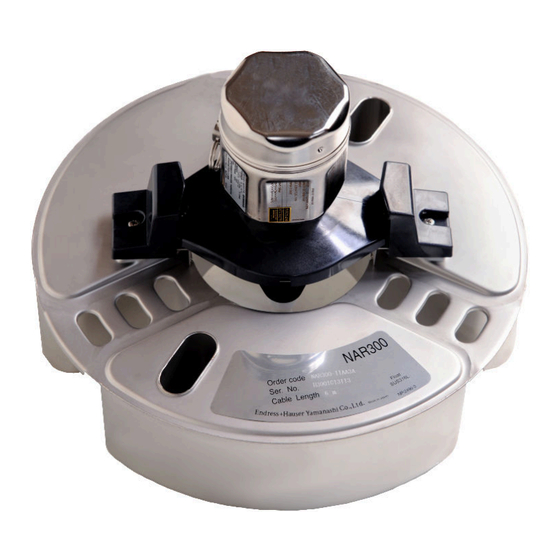
Oil leak detector float sensor
Hide thumbs
Also See for NAR300:
- Operating instructions manual (64 pages) ,
- Operating instructions manual (48 pages) ,
- Operating instructions manual (52 pages)
Table of Contents
Advertisement
Quick Links
KA01577G/00/EN/02.23-00
71614572
2023-05-15
Products
Brief Operating Instructions
NAR300 system
Oil leak detector float sensor
These Instructions are Brief Operating Instructions; they are
not a substitute for the Operating Instructions pertaining to
the device.
Detailed information about the device can be found in the
Operating Instructions and the other documentation:
Available for all device versions via:
• Internet:
www.endress.com/deviceviewer
• Smart phone/tablet: Endress+Hauser Operations App
Solutions
Services
Advertisement
Table of Contents

Related Manuals for Endress+Hauser NAR300


Summary of Contents for Endress+Hauser NAR300
- Page 1 Operating Instructions pertaining to the device. Detailed information about the device can be found in the Operating Instructions and the other documentation: Available for all device versions via: • Internet: www.endress.com/deviceviewer • Smart phone/tablet: Endress+Hauser Operations App...
- Page 2 NAR300 system Order code: XXXXX-XXXXXX Ser. no.: XXXXXXXXXXXX Ext. ord. cd.: XXX.XXXX.XX Serial number www.endress.com/deviceviewer Endress+Hauser Operations App A0023555 Endress+Hauser...
-
Page 3: Table Of Contents
Mounting the NAR300 system ........ -
Page 4: Document Information
Document information NAR300 system Document information Symbols used 1.1.1 Safety symbols DANGER This symbol alerts you to a dangerous situation. Failure to avoid this situation will result in serious or fatal injury. WARNING This symbol alerts you to a dangerous situation. Failure to avoid this situation can result in serious or fatal injury. - Page 5 NAR300 system Document information Torx screwdriver Allen key Open-ended wrench 1.1.4 Symbols for certain types of information and graphics Permitted Procedures, processes or actions that are permitted Preferred Procedures, processes or actions that are preferred Forbidden Procedures, processes or actions that are forbidden Tip...
-
Page 6: Documentation
Document information NAR300 system Documentation The following documents can be found in the Download area of our website (www.endress.com/downloads). For an overview of the scope of the associated Technical Documentation, refer to the following: W@M Device Viewer (www.endress.com/deviceviewer): Enter the serial number from nameplate 1.2.1... -
Page 7: Basic Safety Instructions
NAR300 system Basic safety instructions Basic safety instructions Basic instructions regarding safety 2.1.1 Requirements for the personnel The personnel must fulfill the following requirements for its tasks: ‣ Trained, qualified specialists must have a relevant qualification for this specific function and task. -
Page 8: Product Safety
Product safety The NAR300 system is designed in accordance with GEP (Good Engineering Practice) to meet the latest safety requirements, and it has been tested to ensure that it is ready to be used safely before being shipped from the factory. The NAR300 system meets general safety standards and legal requirements. -
Page 9: Product Description
Product description The NAR300 system is installed in a pit inside the oil-retaining wall of a tank or in a sump pit near a plant or a pump yard, and it provides the ultimate leak detection function for oils, such as petrochemicals and vegetable oils. -
Page 10: Incoming Acceptance And Product Identification
• Do the nameplate data match the ordering information on the delivery note? • If required (see nameplate): Are the Safety Instructions (XA) enclosed? If one or more of these conditions are not satisfied, contact your Endress+Hauser Sales Center or distributor. - Page 11 NAR300 system Incoming acceptance and product identification A0039861 3 Nameplate for NAR300 NAR300 nameplate for FM NAR300 nameplate for ATEX / IECEx Order code Serial number Endress+Hauser...
- Page 12 : Refer to Ex instruction manual XA01742G-*/08/EN Endress+Hauser Yamanashi Co., Ltd Yamanashi 406-0846 Made in Japan NP-2744-1 A0039862 4 Nameplate for NRR261 NRR261 nameplate for FM (NAR300 integrated type) NRR261 nameplate for ATEX / IECEx (NAR300 integrated type) Order code Endress+Hauser...
- Page 13 NAR300 system Incoming acceptance and product identification Serial number Power supply voltage Manufacturing date Endress+Hauser...
- Page 14 Incoming acceptance and product identification NAR300 system NRR262 Order code Seri. no. AIS Class I, Div. 1, Gp. C, D Class I, Zone 0, AEx [ia] IIB Ambient temperature: -20°C ~ + 60°C IP20 Intrinsically safe circuit: Uo = 28 V Io = 85 mA Po = 595 mW Co = 0.083 F Lo = 2.4mH...
- Page 15 Made in Japan NP-2768 NP-2769 A0039865 6 NAR300/NRR261 nameplates NAR300 nameplate for JPN Ex NRR261 nameplate for JPN Ex (NAR300 integrated type) NRR261 nameplate for JPN Ex (NAR300 separate type) Order code Serial number Power supply voltage Manufacturing date Endress+Hauser...
-
Page 16: Manufacturer Address
Endress+Hauser Yamanashi Co.,Ltd. Yamanashi 406-0846 NP - 2770 Made in Japan A0039866 7 NRR262 nameplate for JPN Ex Order code Serial number Power supply voltage Manufacturing date Manufacturer address Endress+Hauser Yamanashi Co., Ltd. 406-0846 862-1 Mitsukunugi, Sakaigawa-cho, Fuefuki-shi, Yamanashi Endress+Hauser... -
Page 17: Storage And Transport
NAR300 system Incoming acceptance and product identification Storage and transport 4.4.1 Transport NOTICE The housing may become damaged or dislodged. Risk of injury ‣ When transporting the device to the measuring point, either use the device' s original packaging or hold by the process connector. -
Page 18: Installation
5.1.1 Handling precautions Always use both hands to hold the float when carrying NAR300. Do not lift or hold by any of the components shown in the figure below, and do not lift by the upper portion of the float sensor. - Page 19 5.1.2 Float guide mounting NAR300 may be mounted on a float guide that has been installed for existing products (CFD10, CFD30, UFD10, NAR291, NAR292). If the float guide is shorter than 2 000 mm (78.74 in), either cut and use it or follow the protocol for when it is 2 000 mm (78.74 in) or longer and contact your nearest Endress...
- Page 20 Installation NAR300 system 5.1.3 NRR261-4xx (integrated type) cable mounting Mounting procedure Remove the intrinsically safe terminal box cover [7] and the circuit board guard [6]. Insert the float sensor cable [4] into the cable gland [1] and cable entry for the intrinsically safe terminal box.
- Page 21 NAR300 system Installation A0039881 10 NRR261-4xx cable mounting Cable gland mounting example Float sensor cable Cable holder Circuit board guard Intrinsically safe terminal box cover Cable gland (Ex d) (supplied with JPN Ex specifications only) Since the cable gland [1] shown in the diagram is not supplied with products that do not have JPN Ex specifications, a water-proof cable gland that is IP67 or higher must be procured separately.
- Page 22 Installation NAR300 system 5.1.4 NAR300-x5xxxx and sensor I/F Ex box cable mounting Mounting procedure Remove the intrinsically safe terminal box cover [5] and the circuit board guard [4]. Insert the float sensor cable [2] into the cable gland [1] and cable entry for the intrinsically safe terminal box.
- Page 23 NAR300 system Installation A0039882 11 NAR300-x5xxxx and sensor I/F Ex box cable mounting Cable gland Shielded cable for NRR261/262 (must be procured separately) Cable gland mounting example Float sensor cable Cable holder Circuit board guard Intrinsically safe terminal box cover...
- Page 24 Installation NAR300 system 5.1.5 NRR261-5xx cable mounting Mounting procedure Remove the intrinsically safe terminal box cover [6] and the terminal block cover [5]. Insert the float sensor cable [2] into the cable gland [1] and cable entry for the intrinsically safe terminal box.
- Page 25 NAR300 system Installation A0039883 12 NRR261-5xx cable mounting Cable gland mounting example Terminal block cover Intrinsically safe terminal box cover Cable gland (Ex d) (supplied with JPN Ex specifications only) Since the cable gland [1] shown in the diagram is not supplied with products that do not have JPN Ex specifications, a water-proof cable gland that is IP67 or higher must be procured separately.
-
Page 26: Adjustment
Installation NAR300 system Adjustment 5.2.1 Verification of detection sensitivity in actual liquid Verification of detection sensitivity when the lower layer is water and the upper layer is If the electrode tip is pulled out of the lower-layer water due to increased thickness of the oil layer, water may cling onto the electrode tip like an icicle even if the electrode tip is in oil. - Page 27 NAR300 system Installation Sensor Input NRR262 Delay Power: Green Timer Alarm: Red (second) Power Output AC90-250V Monitor A0039891 13 Alarm output relay Delay trimmer Cover LED power (green) / alarm (red) Endress+Hauser...
-
Page 28: Electrical Connection
Electrical connection NAR300 system Electrical connection NRR261-4/A/B/C wiring 90 - 250V 2, 3 50/50Hz N.C1 N.O1 COM1 FG H- H+ FEL+ FEL- FRAME GUARD PROBE A0039887 14 Wiring of Ex d [ia] Converter NRR261-4/A/B/C Endress+Hauser... - Page 29 The cable for connecting NAR300 and NRR261 (3) is included with NAR300. The alarm output cable (4) from NRR261 and the power cable (5) to NRR261 are not included and must be procured by the customer. For detailed information on the connection cables, refer to the "Process conditions"...
-
Page 30: Nrr262-4/A/B/C Wiring
Electrical connection NAR300 system NRR262-4/A/B/C wiring Sensor Input NRR262 Delay Power: Green Timer Alarm: Red (second) Power AC90-250V Output Monitor FEL+ FEL- FRAME GUARD PROBE 2, 3 Sensor Input NRR262 N.C COM N.O Delay Power: Green Timer Alarm: Red (second) - Page 31 Although cable (1) that connects NAR300 and a sensor I/F Ex box is included with the device, a cable (2) that connects a sensor I/F Ex box and NRR262 is not included, and it must be procured by the customer.
-
Page 32: Nrr261-5 Wiring
Electrical connection NAR300 system NRR261-5 wiring FEL+ FEL- FRAME GUARD PROBE 90 - 250V 3, 4 50/50Hz N.C1 N.O1 COM1 A0039889 16 Wiring of Ex d [ia] Converter NRR261-5 Endress+Hauser... - Page 33 The cable for connecting NAR300 and the sensor I/F Ex box (1) is included with NAR300. Cable (2) for connecting the sensor I/F Ex box to NRR261, the alarm output cable (3) from NRR261, as well as the power cable (4) to NRR261 are not included and must be procured by the customer.
-
Page 34: Wiring Diagram
Wiring diagram Ex d-type converter system (integrated type) Intrinsically safe-type converter system (separate type) Ex d [ia] converter system (separate type) Protection earth (protective grounding) Float sensor NAR300 Tuning fork driving unit Tuning fork Conductivity detection electrode (sensor) Dedicated cable... - Page 35 NAR300 system Electrical connection Relay Delay circuit Ex [ia] circuit Ex d circuit Current detection Delay trimmer Alarm Sensor I/F Ex box Current signal Converter NRR262 Converter NRR261 (separate type) Endress+Hauser...
-
Page 36: Operating Principles Of Alarm Activation
NAR300 system Operating principles of alarm activation The oil leak detection signal detected by the NAR300 float sensor is converted to a current signal in the converter or the sensor I/F Ex box. After this, it is connected to the current detection circuit via the Ex [ia] safety barrier in the converter. - Page 40 *71614572* 71614572 www.addresses.endress.com...
Need help?
Do you have a question about the NAR300 and is the answer not in the manual?
Questions and answers