Endress+Hauser Oxymax COS22D Operating Instructions Manual
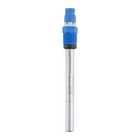
Dissolved oxygen sensor
Hide thumbs
Also See for Oxymax COS22D:
- Operating instructions manual (36 pages) ,
- Brief operating instructions (20 pages) ,
- Operating instructions manual (40 pages)

Related Manuals for Endress+Hauser Oxymax COS22D


Summary of Contents for Endress+Hauser Oxymax COS22D
- Page 1 Operating Instructions Oxymax COS22D Dissolved oxygen sensor BA447C/07/EN/01.11 71098073...
- Page 2 Notes for using this manual Warning instructions and their meaning The structure, signal words and safety colors of the signs comply with the specifications of ANSI Z535.6 ("Product safety information in product manuals, instructions and other collateral materials"). Safety message structure Meaning This symbol alerts you to a dangerous situation.
-
Page 3: Table Of Contents
Accessories....29 Connection accessories ....29 Installation accessories ....29 Endress+Hauser... -
Page 4: Safety Instructions
• Do not operate damaged products and secure them against unintentional commissioning. Mark the damaged product as being defective. • Measuring point faults may only be rectified by authorized and specially trained personnel. • If faults cannot be rectified, the products must be taken out of service and secured against unintentional commissioning. Endress+Hauser... -
Page 5: Operational Safety
• Oxygen sensor with watering cap (filled with tap water) for protecting the membrane • Electrolyte, 1 bottle, 10 ml (0.34 fl.oz.) • Brief Operating Instructions • Operating Instructions on CD If you have any questions, please contact your supplier or your sales center responsible. Endress+Hauser... -
Page 6: Certificates And Approvals
Identification Certificates and approvals 2.3.1 Approval for use in hazardous areas Version COS22D-BA ATEX 1G Ex ia IIC T3/T4/T6 Ga Designated authority EXAM BBG Prüf- und Zertifizier GmbH Bochum a0014925 Endress+Hauser... - Page 7 COS22D-****23 Membrane, O-rings COS22Z-*2*3 Membrane, O-rings Note for hazardous area versions: For operation in FDA processes, another FDA-approved seal must be installed before the process seal (e.g. CPA442). Doing so will sufficiently separate the process from the Ex connection. Endress+Hauser...
-
Page 8: Installation
The sensor must be installed with an inclination angle of at least 10 ˚ to the horizontal in an assembly, support or a corresponding process connection. Other inclination angles are not permitted. Do not install the sensor overhead. Observe the instructions for installing sensors in the Operating Instructions for the assembly used. Endress+Hauser... -
Page 9: Installation Instructions
Installation instructions 3.3.1 Measuring system A complete measuring system comprises: • An Oxymax COS22D oxygen sensor • A transmitter, e.g. Liquiline CM42 • A corresponding measuring cable, e.g. CYK10 • Optional: an assembly, e.g. permanent installation assembly CPA442, flow assembly CPA240, or... - Page 10 Otherwise you might unscrew the membrane cap. This will then remain in the assembly or process. ► Avoid exerting excessive tensile force on the cable (e.g. from jerky pulling). ► Select an installation location that is easy to access for later calibrations. Endress+Hauser...
-
Page 11: Installation Examples
To prevent measured error with trace measurements, pay particular attention to complete ventilation of the assembly. a0005721 Fig. 4: Bypass installation Main line Medium removal 3, 6 Manually actuated or solenoid valves Sampling Flow assembly with installed sensor a0005720 Fig. 3: Flow assembly CPA240 with protective cover Medium return Endress+Hauser... - Page 12 120 mm. The assembly has a low sampling volume and, with the 6-mm connections, it is best suited for residual oxygen measurement in water treatments and boiler feedwater. The flow comes from below. a0014081 Fig. 5: Flow assembly Built-in sensor Drain Wall mount (clamp D29) Inflow Endress+Hauser...
-
Page 13: Post-Installation Check
► Sensor and cable undamaged? ► Compliance with permissible sensor installation position? ► Is the sensor installed in an assembly and is not suspended from the cable? ► Avoid the penetration of moisture by fitting the protective cap to the immersion assembly. Endress+Hauser... -
Page 14: Wiring
04 ATEX E 121 X. The corresponding EC declaration of conformity is part of this document. • The certified oxygen sensor Oxymax COS22D-BA***** may be used in conjunction with the measuring cable CYK10-G**1 on certified, intrinsically safe, digital sensor circuits of the transmitter Liquiline M CM42-*G********* only. - Page 15 Wiring a0010056 Fig. 7: Endress+Hauser...
-
Page 16: Connection At The Transmitter
Are all the screws terminals properly tightened? Tighten Are all the cable entries installed, tightened and sealed? For cable entries lateral: cable loops downwards for water to be able to drip off. Are all the cable entries installed downwards or lateral? Endress+Hauser... -
Page 17: Function
5.1.2 Sensor design a0011869 Fig. 9: Exploded view Plug-in head Membrane body Process seal 10.77 x 2.62 mm Thrust collar Shaft sleeve Process connection Pg 13.5 Sensor shaft Glass portion with anode and O-ring 8.5 x 1.5 mm cathode Endress+Hauser... - Page 18 The sensor is shipped with a standard membrane body, which can be used for all common applications. The membrane is pretensioned at the factory and can be installed immediately. Electrolytes are version-specific and cannot be mixed in a single application! Endress+Hauser...
-
Page 19: Calibration
Pay particular attention to the software settings for the stability criteria for calibration. Then insert the sensor into the medium. Make sure you comply with the instructions for calibration in the Operating Instructions of the transmitter. Endress+Hauser... - Page 20 1650 (5410) 0.825 150 (490) 0.982 700 (2300) 0.922 1200 (3940) 0.869 1700 (5580) 0.820 200 (660) 0.977 750 (2460) 0.916 1250 (4100) 0.864 1750 (5740) 0.815 250 (820) 0.971 800 (2620) 0.911 1300 (4270) 0.859 1800 (5910) 0.810 Endress+Hauser...
- Page 21 Calibration value C = 8.88 mg/l. You do not need factor K in the table if your measuring device returns the absolute air pressure (air pressure depending on altitude) as the measured value. The formula for calculation is then: C = S Endress+Hauser...
-
Page 22: Commissioning
Connect the sensor to the transmitter. Switch on the transmitter. When the sensor is connected to the transmitter, the polarization takes place automatically after the power-up of the transmitter. Wait for the polarization time to run out. Endress+Hauser... -
Page 23: Calibration
Otherwise, double the length of time to the next inspection. Proceed as per Point 1 after two, four and/or eight months. In this way, you can determine the optimum calibration interval for your sensor. In any case, calibrate the sensor at least once a year. Endress+Hauser... -
Page 24: Maintenance
Proceed similarly after two, four and/or eight months. In this way, you can determine the optimum maintenance interval for your sensor. Particularly for widely varying process conditions, damage of the membrane can occur even within a maintenance cycle. You can recognize this by implausible sensor behavior. Endress+Hauser... -
Page 25: Cleaning The Sensor
Replacing the sealing ring Visible damage to the sealing ring Changing the electrolyte Unstable or implausible measuring signal or fouling of the electrolyte Replacing the membrane cap Membrane is damaged or can no longer be cleaned (hole or overstretching) Endress+Hauser... - Page 26 ► In case of eye contact: Remove contact lenses, flush eyes with water for a few minutes and contact a doctor. ► In case of skin contact: Take off wet clothing immediately, wash the skin or take a shower. Endress+Hauser...
- Page 27 Carry out a reset of the cap counter (see Liquiline Operating Instructions). After replacing the membrane cap, the sensor must be repolarized and recalibrated. Then insert the sensor into the medium and check that no alarm is displayed on the transmitter. Endress+Hauser...
- Page 28 Plug a new glass body (from the membrane kit) into the holder so that it fits. Ensure that you do not damage the electrical contact pins. Fill the membrane body with electrolyte (see preceding section), then screw the shaft sleeve back Endress+Hauser...
-
Page 29: Accessories
• Technical Information TI306/C/07/de Cleanfit CPA450 • Manual retractable assembly for installing 120 mm sensors in tanks and pipes • Technical Information TI183C/07/en Flow assembly for 120 mm sensors • Compact stainless steel assembly with low sampling volume • Order No.: 71042404 Endress+Hauser... -
Page 30: Troubleshooting
Check the cable connection. If the problem displayed value the transmitter display now at 0? persists, send in the sensor. Make sure you comply with the instructions for troubleshooting in the Operating Instructions of the transmitter. If necessary, carry out a test of the transmitter. Endress+Hauser... -
Page 31: Spare Parts And Consumables
Operating Instructions) with the packaging and the transportation documents. No repair without completed "Declaration of contamination"! Disposal The device contains electronic components and must therefore be disposed of in accordance with regulations on the disposal of electronic waste. Observe local regulations. Endress+Hauser... -
Page 32: Technical Data
COS22D-*1 (standard sensor): 40 to 100 nA COS22D-*3 (trace sensor): 210 to 451 nA 10.2.4 Zero current COS22D-*1 (standard sensor): < 0.1 % of the current in air COS22D-*3 (trace sensor): < 0.03 % of the current in air Endress+Hauser... - Page 33 • Measured variable as partial pressure [hPa] or in Vol%: -5 to 90 ˚C (23 to 194 ˚F) • Measured variable as concentration [mg/l]: 0 to 80 ˚C (32 to 176 ˚F) • Measured variable as saturation [%SAT]: -5 to 90 ˚C (23 to 194 ˚F) In accordance with IEC 61298-2 at rated operating conditions Endress+Hauser...
-
Page 34: Environment
10.4.1 Process temperature –5 to +135 ˚C (23 to 275 ˚F) 10.4.2 Process pressure Ambient pressure ... 12 bar (... 174 psi) 10.4.3 Temperature-pressure chart a0011887 Fig. 11: Temperature-pressure chart: A, B, C = Defined ranges of temperature compensation Endress+Hauser... -
Page 35: Mechanical Construction
Stainless steel 1.4435 (AISI 316L) (depending on the design) Titanium Alloy C22 Electrode combination Silver / platinum ® Process seal Viton (FDA-compliant) ® Process seal for ATEX/FM/CSA Viton (not FDA-compliant) ® Seals/O-rings Viton (FDA-compliant) Process seal Perfluoroelastomer with USP88 Class VI Endress+Hauser... - Page 36 Technical data Parts in contact with medium Membrane Silicone (FDA-compliant), PTFE, steel mesh 10.5.3 Process connection Coupling Pg 13.5 10.5.4 Surface roughness < 0.38 μm 10.5.5 Electrolyte COS22D-*1 (standard sensor): slightly alkaline electrolyte COS22D-*3 (trace sensor): neutral electrolyte Endress+Hauser...
-
Page 37: Index
Polarization......18, 22 Polarization time ......33 Endress+Hauser... - Page 38 Process ....... . 34 Process connection ....35–36 Zero current .
- Page 39 Declaration of Hazardous Material and De-Contamination Please reference the Return Authorization Number (RA#), obtained from Endress+Hauser, on all paperwork and RA No. mark the RA# clearly on the outside of the box. If this procedure is not followed, it may result in the refusal of the package at our facility.
- Page 40 BA447C/07/EN/01.11 71098073...
Need help?
Do you have a question about the Oxymax COS22D and is the answer not in the manual?
Questions and answers