Endress+Hauser NAR300 Operating Instructions Manual
Oil leak detector float sensor
Hide thumbs
Also See for NAR300:
- Operating instructions manual (64 pages) ,
- Brief operating instructions (40 pages) ,
- Operating instructions manual (48 pages)

Related Manuals for Endress+Hauser NAR300


Summary of Contents for Endress+Hauser NAR300
- Page 1 Products Solutions Services BA00402G/00/EN/26.24-00 71661262 2024-05-31 Operating Instructions NAR300 system Oil leak detector float sensor...
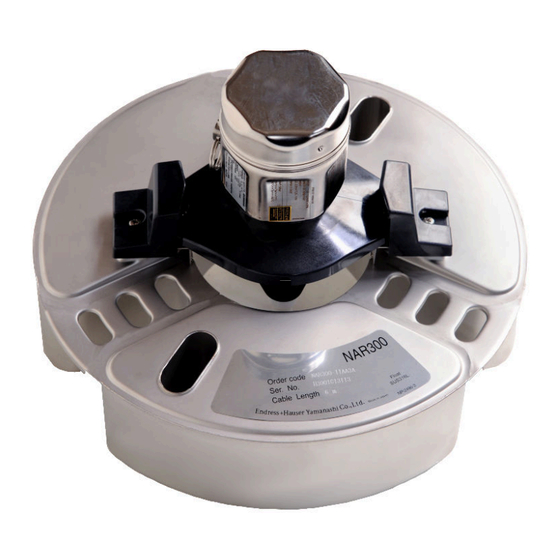
- Page 2 NAR300 system Order code: XXXXX-XXXXXX Ser. no.: XXXXXXXXXXXX Ext. ord. cd.: XXX.XXXX.XX Serial number www.endress.com/deviceviewer Endress+Hauser Operations App A0023555 Endress+Hauser...
-
Page 3: Table Of Contents
Installation conditions ....26 Mounting NAR300 system ....28 Adjustment . -
Page 4: Document Information
Document information NAR300 system Document information Document function These Operating Instructions contain all the information that is required in various phases of the life cycle of the device: from product identification, incoming acceptance and storage, to mounting, connection, operation and commissioning through to troubleshooting, maintenance and disposal. - Page 5 NAR300 system Document information Flat blade screwdriver Torx screwdriver Allen key Open-ended wrench 1.2.4 Symbols for certain types of information and graphics Permitted Procedures, processes or actions that are permitted Preferred Procedures, processes or actions that are preferred Forbidden Procedures, processes or actions that are forbidden Tip...
-
Page 6: Documentation
Document information NAR300 system Documentation The following documents can be found in the Download area of our website (www.endress.com/downloads). For an overview of the scope of the associated Technical Documentation, refer to the following: W@M Device Viewer (www.endress.com/deviceviewer): Enter the serial number from nameplate 1.3.1... -
Page 7: Basic Safety Instructions
NAR300 system Basic safety instructions Basic safety instructions Basic instructions regarding safety 2.1.1 Requirements for the personnel The personnel for installation, commissioning, diagnostics and maintenance must fulfill the following requirements: ‣ Trained, qualified specialists must have a relevant qualification for this specific function and task. -
Page 8: Product Safety
Product safety The NAR300 system is designed in accordance with GEP (Good Engineering Practice) to meet the latest safety requirements, and it has been tested to ensure that it is ready to be used safely before being shipped from the factory. The NAR300 system meets general safety standards and legal requirements. -
Page 9: Product Description
Product description Product description NAR300 system is designed to be installed in a pit within an oil retaining dike, a plant, or a sump pit near a pump yard, where it can provide the ultimate in leak detection function for oils, such as petrochemicals and vegetable oils. The system utilizes two different detection principles, conductivity and tuning fork, to monitor detection status individually. - Page 10 Protection class IP67 (outdoor installation) Power supply Supplied by NRR261 or NRR262 Cable entry • NAR300 (float sensor) side: G1/2, with cable gland • NRR261 or NRR262 (converter) side: G1/2, NPT1/2, M20 Weight 3.2 kg (7.1 lb) Materials Housing/cover: Aluminum casting 3.2.3...
-
Page 11: Process Conditions
Built-in (power supply arrester) Weight Approx. 0.6 kg (1.3 lb) Materials Housing: Plastic Process conditions 3.3.1 Float sensor NAR300 / sensor I/F Ex box Item Description Requirements for • Density is at least 0.7 g/cm but less than 1.0 g/cm substance detection •... -
Page 12: Delivery Example By Order Code
Product description NAR300 system Delivery example by order code Delivery example 1 Float sensor order code Converter order code NAR300- * 1* * 2 / 3 A NRR261-A/B/C/4 NRR261 U-bolt Float sensor Check tool (accessory) Float guide (bar) packaged separately... - Page 13 Sensor I/F Ex box Check tool (accessory) • The sensor I/F Ex box is included in the order code NAR300-x5xxxx. The intrinsically safe system is used in combination with NRR262. • A cable gland (water-proof connection) is only included with the sensor I/F Ex box or NRR261 with JPNEx specifications.
- Page 14 Sensor I/F Ex box Check tool (accessory) • The sensor I/F Ex box is included in the order code NAR300 - x5xxxx. The Ex d [ia] system is used in combination with NRR261 - 5**. • A cable gland (water-proof connection) is only included with the sensor I/F Ex box or NRR261 with JPNEx specifications.
-
Page 15: Detection Sensitivity
If the substance to be detected is gasoline, or if the system is to be used in an atmosphere that is constantly exposed to volatile oil vapor, contact your Endress+Hauser Sales Center and order the gasoline application specifications under special specifications. -
Page 16: Incoming Acceptance And Product
• Do the nameplate data match the ordering information on the delivery note? • If required (see nameplate): Are the Safety Instructions (XA) enclosed? If one or more of these conditions are not satisfied, contact your Endress+Hauser Sales Center or distributor. - Page 17 NAR300 system Incoming acceptance and product identification A0039861 3 Nameplate for NAR300 NAR300 nameplate for FM NAR300 nameplate for ATEX / IECEx Order code Serial number Endress+Hauser...
- Page 18 Endress+Hauser Yamanashi Co., Ltd Yamanashi 406-0846 Made in Japan NP-2744-1 A0039862 4 Nameplate for NRR261 NRR261 nameplate for FM (NAR300 integrated type) NRR261 nameplate for ATEX / IECEx (NAR300 integrated type) Order code Serial number Power supply voltage Manufacturing date Endress+Hauser...
- Page 19 NAR300 system Incoming acceptance and product identification NRR262 Order code Seri. no. AIS Class I, Div. 1, Gp. C, D Class I, Zone 0, AEx [ia] IIB Ambient temperature: -20°C ~ + 60°C IP20 Intrinsically safe circuit: Uo = 28 V Io = 85 mA Po = 595 mW Co = 0.083 F Lo = 2.4mH...
- Page 20 Made in Japan NP-2768 NP-2769 A0039865 6 NAR300/NRR261 nameplates NAR300 nameplate for JPN Ex NRR261 nameplate for JPN Ex (NAR300 integrated type) NRR261 nameplate for JPN Ex (NAR300 separate type) Order code Serial number Power supply voltage Manufacturing date NRR262 Order code Ser.
-
Page 21: Manufacturer Address
NAR300 system Incoming acceptance and product identification Manufacturer address Endress+Hauser Yamanashi Co., Ltd. 406-0846 862-1 Mitsukunugi, Sakaigawa-cho, Fuefuki-shi, Yamanashi Storage and transport 4.4.1 Storage conditions • Storage temperature: –20 to +60 °C (–4 to 140 °F) • Store the device in its original packaging. -
Page 22: Installation
Installation NAR300 system Installation NAR300 system dimensions 5.1.1 Dimensions of NAR300 float sensor 200 (7.87) 250 (9.84) 304 (11.97) A0039876 8 Float sensor NAR300 dimensions. Unit of measurement mm (in) Float sensor cover Endress+Hauser... - Page 23 NAR300 system Installation 5.1.2 Dimensions of Ex d [ia] converter NRR261 Only NRR261 with JPN Ex explosion-proof specifications are delivered with a cable gland (external diameter of compatible cables: φ12 to 16 mm (0.47 to 1.02 in)). Use the order code of Ex d [ia] converter NRR261 to specify the conduit connection port.
- Page 24 Installation NAR300 system 5.1.3 Dimensions of Ex [ia] converter NRR262 NRR262 is installed indoors, such as in the instrument room, and it can be mounted easily with two M4 screws. It can also be snapped into place with just one touch by using DIN rail EN50022 (sold separately).
- Page 25 G1/2 / NPT1/2: 85 mm (3.35 in), M25: 107 mm (4.21 in) U-bolt (JIS F3022 B50 material: iron (chromate), 2 nuts and 2 flat washers included) 4-φ12 mm (0.47 in) hole Use the order code of float sensor NAR300 to specify the conduit connection port. ...
-
Page 26: Installation Conditions
Float guide Chain Weight Float sensor NAR300 Discharge nozzle (100 mm (3.94 in) or longer) Dedicated cable (included with NAR300) Valve Drainage groove Ex [ia] sensor I/F Ex box NRR261 (Ex d [ia] converter) (integrated type) U-bolt (JIS FF3022 B50) - Page 27 9. If the pit is too large, divide the pit using an oil separator. Oil leakage cannot be detected unless the volume of oil outflow increases in proportion to the surface area. 10. NAR300, NRR261, and sensor I/F Ex box must be installed at least 50 cm (1.64 ft) apart from each other.
-
Page 28: Mounting Nar300 System
5.3.1 Handling precautions When transporting NAR300, be sure to hold the float with both hands. Avoid holding the parts shown in the diagram below, and do not lift by the top of the float sensor. In addition, do not rotate the housing. Doing so may cause the device to malfunction. - Page 29 5.3.2 Mounting the float guide NAR300 can be mounted onto a float guide that has been installed for existing products (CFD10, CFD30, UFD10, NAR291, NAR292). The float guide is 2 000 mm (78.74 in) in size. If a length shorter than 2 000 mm (78.74 in) is required for use, cut it to size.
- Page 30 Installation NAR300 system 5.3.3 NRR261-4xx (integrated type) cable mounting Mounting procedure 1. Remove the intrinsically safe terminal box cover [5] and the circuit board guard [4]. 2. Pass the float sensor cable [2] through the cable gland [1] and the cable entry of the intrinsically safe terminal box.
- Page 31 7. Attach the circuit board guard and close the cover of the intrinsically safe terminal box. This completes the mounting procedure. A0039882 16 NAR300-x5xxxx and sensor I/F Ex box cable mounting Cable gland Shielded cable for NRR261/262 (must be procured separately) Cable gland (waterproof connection) Float sensor cable...
- Page 32 Installation NAR300 system 5.3.5 NRR261-5xx cable mounting Mounting procedure 1. Remove the intrinsically safe terminal box cover [4] and the terminal block cover [3]. 2. Pass the float sensor cable [2] through the cable gland [1] and the cable entry of the intrinsically safe terminal box.
-
Page 33: Adjustment
NAR300 system Installation Adjustment 5.4.1 Verification of detection sensitivity with actual liquid Verification of detection sensitivity with water in the bottom layer and oil in the top layer When the tip of an electrode is pulled out from the water in the bottom layer, water may cling to the electrode tip like an icicle even when it is in the oil layer due to increased thickness of the oil layer, and this will increase the detection sensitivity by 1 to 2 mm. -
Page 34: Electrical Connection
FRAME GUARD PROBE A0039887 19 Wiring of Ex d [ia] converter NRR261-4/A/B/C Float sensor NAR300-x1xxxx Ex d [ia] converter NRR261 (integrated type) Blue 1 (already wired upon delivery), screw (M3) Blue 2 (already wired upon delivery), screw (M3) Green, screw (M3) - Page 35 50/60 Hz during normal times and 250 V during emergencies. 4. Cable (3) which connects NAR300 and NRR261 is included with NAR300. Alarm output cable (4) from NRR261 and power supply cable (5) to NRR261 are not included and must be procured by the customer. For more details on connection cables, refer to "Process conditions."...
-
Page 36: Nrr262-4/A/B/C Wiring
Monitor A0039888 20 Wiring of Ex [ia] converter NRR262-4/A/B/C Float sensor NAR300-x5xxxx (sensor I/F Ex box is also included in the code) Sensor I/F Ex box Ex [ia] converter NRR262 Green, screw (M3) (see Note 1 below) Output to NRR262, screw (M3) - Page 37 50/60 Hz during normal times and 250 V during emergencies. 4. While cable (1) for connecting NAR300 and sensor I/F Ex box is included with the device, cable (2) for connecting sensor I/F Ex box and NRR262 is not included with the device and must be procured by the customer.
-
Page 38: Nrr261-5 Wiring
A0039889 21 Wiring of Ex d [ia] converter NRR261-5 Float sensor NAR300-x5xxxx (sensor I/F Ex box is also included in the code) Sensor I/F Ex box Ex d [ia] converter NRR261 (separate type) Green, screw (M3) (see Note 1 below) - Page 39 50/60 Hz during normal times and 250 V during emergencies. 5. Cable (1) which connects NAR300 and sensor I/F Ex box is included with NAR300. Cable (2) which connects sensor I/F Ex box and NRR262, alarm out cable (3) from NRR261, and power supply cable (4) for NRR261 are not included and must be procured by the customer.
-
Page 40: Wiring Diagram
Wiring diagram Explosion proof-type converter system (integrated type) Intrinsically safe-type converter system (separate type) Intrinsically safe, explosion proof-type converter (separate type) Protective earth (protective grounding) Float sensor NAR300 Tuning fork drive unit Tuning fork Conductivity detection electrode (sensor) Dedicated cable... -
Page 41: Alarm Activation Principle
Electrical connection Alarm activation principle An oil leak detection signal detected by NAR300 float sensor is converted into a current signal inside the converter or sensor I/F Ex box. The signal is then connected to the current detection circuit through the intrinsically safe safety barrier inside the converter. In the... -
Page 42: Diagnostics And Troubleshooting
Diagnostics and troubleshooting NAR300 system Diagnostics and troubleshooting Fail-safe (alarm is output when there is no oil leak) The following situations may cause an alarm to be output even when there is no oil leak. Item Description Frozen pit water An alarm is activated when the conductivity sensor detects an insulator due to frozen pit water. - Page 43 NAR300 system Diagnostics and troubleshooting Item Description Oil leak during snowfall No alarm will be activated if there is snow floating on the oil layer surface, as the conductivity sensor will recognize water due to the moisture from the melted snow.
-
Page 44: Operation Check
Diagnostics and troubleshooting NAR300 system Operation check To perform an operation check, assign one person to operate the float sensor and another person to check the operation of the on-site sensor I/F Ex box or Ex d converter NRR261. Avoid electrostatic charge on the float. - Page 45 NAR300 system Diagnostics and troubleshooting Operation checker (specialty tool) Mount the operation checker by screwing it in the tuning fork unit. The operation checker can be ordered under Item No. 71137732. A0039894 25 Operation checker (specialty tool) Operation checker...
- Page 46 Diagnostics and troubleshooting NAR300 system 7.3.1 Operation check flowchart A0047844 The voltage upon turning on the power supply is DC20 ± 1V in ATEX, IECEx, FM, and JPN Ex specifications, but this will change to DC18 ± 2V after several seconds.
- Page 47 NAR300 system Diagnostics and troubleshooting Before performing an alarm operation check, take measures to prevent the alarm system from being affected even when an oil leak alarm is activated. For the operation check process, see "Operation check flowchart" in the previous section. The diagram below shows the checkpoints for the voltage checks indicated in the flowchart.
-
Page 48: Cleaning The Conductivity Sensor Unit
NAR300 system Cleaning the conductivity sensor unit Normally, NAR300 checks the conduction state between the electrode tip and the float body; if there is conduction, it recognizes "water" and if there is no conduction, it recognizes "oil or air." Since the electrode holder is connected to the float body, it determines that "water"... -
Page 49: Maintenance
8.1.2 Periodic maintenance While the NAR300 float sensor is not easily affected by deposits or adhered material, conduct overall periodic inspections of the cable and wiring, etc., semi-annually along with an operation check as follows. -
Page 50: Repair
General information on repairs 9.1.1 Repair concept The Endress+Hauser repair concept assumes that the devices have a modular design and that repairs can be done by the Endress+Hauser Service Department or specially trained customers. Spare parts are contained in suitable kits. They also come with relevant replacement instructions. -
Page 51: Return
NAR300 system Repair Return The requirements for safe device return can vary depending on the device type and national legislation. 1. Refer to the website for more information: http://www.endress.com/support/return-material 2. Return the device if repairs or a factory calibration are required, or if the wrong device was ordered or delivered. -
Page 52: Accessories
The float guide is 2 000 mm (78.74 in) in size. If a length shorter than 2 000 mm (78.74 in) is required for use, cut it to size. If a float guide longer than 2 000 mm (78.74 in) is required, contact your Endress+Hauser Sales Center. 200 (7.87) (0.39) -
Page 53: U-Bolt / Cable Gland
U-bolt (JIS F3022 B50) is used when mounting the converter. Have a pipe with an internal diameter of 50A (2B φ60.5 mm (198.5 in)) ready. Tighten and secure the cable gland after inserting the cable from NAR300. A0039892 29... -
Page 54: Index
Cleaning NAR300 system ......28 Exterior cleaning ......49... - Page 56 *71661262* 71661262 www.addresses.endress.com...
Need help?
Do you have a question about the NAR300 and is the answer not in the manual?
Questions and answers