Endress+Hauser Turbimax CUS71D Operating Instructions Manual
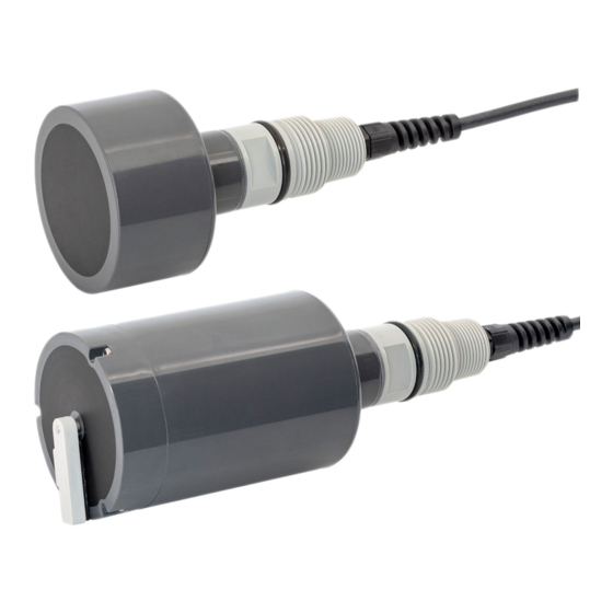
Ultrasonic interface sensor, immersion sensor for interface measurement
Hide thumbs
Also See for Turbimax CUS71D:
- Operating instructions manual (32 pages) ,
- Operating instructions manual (32 pages)

Subscribe to Our Youtube Channel
Related Manuals for Endress+Hauser Turbimax CUS71D


Summary of Contents for Endress+Hauser Turbimax CUS71D
- Page 1 Operating Instructions Turbimax CUS71D Ultrasonic interface sensor Immersion sensor for interface measurement BA490C/07/EN/02.11 71155719...
- Page 2 Endress+Hauser...
-
Page 3: Table Of Contents
Turbimax CUS71D Table of contents Safety instructions ....4 Technical Data....28 Designated use . -
Page 4: Safety Instructions
Safety instructions Turbimax CUS71D Safety instructions Designated use CUS71D is an immersion sensor designed for interface measurement in water and wastewater. The sensor is particularly suited for use in the following applications: • Wastewater treatment: primary clarifier, sludge thickener, secondary clarifier •... -
Page 5: Notes On Safety Icons And Symbols
Turbimax CUS71D Safety instructions Notes on safety icons and symbols Warning! This symbol alerts you to hazards that can cause serious damage to the instrument or to persons if ignored. Caution! " This symbol alerts you to possible faults which could arise from incorrect operation. They could cause damage to the instrument if ignored. -
Page 6: Identification
Scope of delivery The scope of delivery comprises: • 1 sensor Turbimax CUS71D in the ordered version • 1 Operating Instructions BA490C/07/EN If you have any questions, please contact your supplier or your local sales center. Certificates and approvals Declaration of conformity The product meets the requirements of the harmonized European standards. -
Page 7: Installation
Turbimax CUS71D Installation Installation Incoming acceptance, transport, storage • Make sure the packaging is undamaged! • Inform the supplier about any damage to the packaging. Keep the damaged packaging until the matter has been settled. • Make sure the contents are undamaged! •... -
Page 8: Installation Instructions
Turbimax CUS71D Installation instructions 3.3.1 Measuring system A complete measuring system comprises: • Ultrasonic sensor Turbimax CUS71D • Multi-channel transmitter Liquiline CM44x and optional: • Weather protection roof CYY101 • Holder system Flexdip CYH11 • Fixed or rotatable immersion pipe Flexdip CYA112 a0014923 Fig. - Page 9 Turbimax CUS71D Installation 3.3.2 Measuring system with pendulum holder a0015156 Abb. 4: Measuring system with pendulum holder Holder system Flexdip CYH112 (cross clamp) Assembly Flexdip CYA112 with CUS71D Holder system Flexdip CYH112 (pendulum holder) PVC wiper (C-UA 100826-61) The PVC wiper (C-UA 110818-60) protects the ultrasonic sensor from getting damaged by the surface skimmer.
-
Page 10: Installation Conditions
Installation Turbimax CUS71D Installation conditions Basin configuration 6° a0002181 Fig. 5: Basin configuration Sensor Minimum distance of sensor to basin wall = 45 cm (1.48 ft.) Reference point e.g. water surface Zero point Basin depth Opening angle of ultrasonic cone, 6°... -
Page 11: Post-Installation Check
Turbimax CUS71D Installation Circular Clarifier a0015232 Fig. 6: Basin configuration in circular clarifier View from top Cross section Surface skimmer Sensor Walk way Hand rail Sensor mounting Surface skimmer Bottom rake Bottom rake Rake direction Post-installation check • Sensor and cable undamaged? •... -
Page 12: Wiring
Wiring Turbimax CUS71D Wiring Warning! • The electrical connection must only be carried out by a certified electrician. • Technical personnel must have read and understood the instructions in this manual and must adhere to them. • Ensure that there is no voltage at the power cable before beginning the connection work. -
Page 13: Device Description
Turbimax CUS71D Device description Device description Sensor design The sensor is designed for continuous in-situ determination of interfaces. The sensor includes all necessary modules: • Power supply • Ultrasonic source sends the measurement signals. • Ultrasonic receiver receives the measurement signals, digitalizes and converts the signals to a measurement value. -
Page 14: Calibration
Device description Turbimax CUS71D Calibration 5.5.1 Factory calibration The sensor is precalibrated when leaving the factory. After adaption of the basin parameters, the sensor can be used in a wide range of applications without additional calibration. The factory calibration cannot be deleted and can be retrieved at any time. All other calibrations - performed as customized calibrations - are referenced to this factory calibration. -
Page 15: Commissioning
Commissioning Commissioning Firmware update Turbimax CUS71D needs a firmware version "01.02.02-0048" or later. Your current firmware version can be found at: Menu/Diagnostics/System information/Software version If your controller is equipped with an older firmware version you have to perform a firmware update. -
Page 16: Basic Settings
Commissioning Turbimax CUS71D Basic settings After switching on the controller you have to perform some settings to get correct measurement Path: Menu/Setup/Inputs/UIS/Tank configuration The menu Tank configuration defines tank depth and zero adjust. The quality of the measuring results depends on the accuracy of these inputs. - Page 17 Turbimax CUS71D Commissioning Enter the Zero adjust (distance from the waterline to the sensor diaphragm) Outside the Blanking zone (above Upper window limit and below Lower window limit) the permanent echo signals are blanked as interference signals. For upper and lower window limit enter the distance to the waterline.
- Page 18 Commissioning Turbimax CUS71D Path: Menu/Setup/Inputs/UIS/Sensor signal The parameters in the menu Sensor signal are factory preset. If measurement failures are observed the parameters can be adjusted. Acoustic control • Automatic Automatic amplification control • Manual Manual amplification control In automatic mode you cannot modify the parameter Current gain.
- Page 19 Turbimax CUS71D Commissioning The Refresh rate determines the time span to update the current measurement. You can select 2, 4, 6, or 8 seconds. Damping This parameter establishes the number of updates that are averaged to determine the current measurement. It is used to remove the effects of random fluctuations caused by settling or disturbed material.
- Page 20 Commissioning Turbimax CUS71D You can change the parameters of the Tank zone. Gain band establishes the maximum amount that Current gain (with Automatic ON) can vary once the initial gain level has been established. Enter a value from 5 to 30.
- Page 21 Turbimax CUS71D Commissioning Range above bottom establishes a zone near the bottom of tank that permits special handling of a dominant signal that originates from the tank floor. This signal will be suppressed for the calculation of the measuring value.
- Page 22 Commissioning Turbimax CUS71D Around the interface you can define a window entering a distance above and below the interface. The signal that is inside the window is given preferential consideration. You can enter a distance from 0.0 to 10.0 m.
- Page 23 Turbimax CUS71D Commissioning Alarm delay echo loss establishes the amount of time that the sensor must experience a loss of echo before initiating the echo loss action. You can enter a time from 0 to 255 minutes. Reboot track performs a new initialization of the sensor.
-
Page 24: Maintenance
Maintenance Turbimax CUS71D Maintenance You have to perform maintenance tasks at regular intervals. We recommend setting the maintenance times in advance in an operations journal or log. The maintenance cycle primarily depends on the system, the installation conditions and the medium in which measurement takes place. -
Page 25: Accessories
Turbimax CUS71D Accessories Accessories Assemblies Wastewater assembly Flexdip CYA112 • Modular assembly system for sensors in open basins, channels and tanks • Versions in stainless steel or PVC • Ordering acc. to product structure (Technical Information TI432C/07/en) PVC scraper for flexible mounting •... -
Page 26: Troubleshooting
Troubleshooting Turbimax CUS71D Troubleshooting Troubleshooting instructions You must take the entire measuring point into account when troubleshooting: • Transmitter • Electrical connections and cables • Assembly • Sensor The possible causes of error indicated in the table below primarily refer to the sensor. -
Page 27: Return
Turbimax CUS71D Troubleshooting Return If the sensor has to be repaired, please return it cleaned to the sales center responsible. Please use the original packaging, if possible. Before returning the device, please clarify all formalities - such as obtaining an identification number - with your sales center. -
Page 28: Technical Data
Technical Data Turbimax CUS71D Technical Data 10.1 Input Measured variable Standard sensor Interface Sensor with wiper Interface Sensor with wiper and turbidity Interface measurement Turbidity Measuring ranges Standard sensor 0.3 to 10.0 m (1.0 to 32 ft) Sensor with wiper 0.3 to 10.0 m (1.0 to 32 ft) -
Page 29: Index
Turbimax CUS71D Index Accessories ........25 Safety icons . - Page 30 Turbimax CUS71D Endress+Hauser...
- Page 31 Erklärung zur Kontamination und Reinigung Please reference the Return Authorization Number (RA#), obtained from Endress+Hauser, on all paperwork and mark the RA# clearly on the outside of the box. If this procedure is not followed, it may result in the refusal of the package at our facility.
- Page 32 BA490C/07/EN/02.11 71155719 FM+SGML 6.0 71155719...
Need help?
Do you have a question about the Turbimax CUS71D and is the answer not in the manual?
Questions and answers