Endress+Hauser NAR300 Operating Instructions Manual
Oil leak detector float sensor
Hide thumbs
Also See for NAR300:
- Operating instructions manual (64 pages) ,
- Brief operating instructions (40 pages) ,
- Operating instructions manual (48 pages)

Subscribe to Our Youtube Channel
Related Manuals for Endress+Hauser NAR300


Summary of Contents for Endress+Hauser NAR300
- Page 1 Products Solutions Services BA00403G/00/EN/10.22-00 71559868 2022-03-18 Operating Instructions NAR300 system for high temperature Oil leak detector float sensor...
- Page 2 NAR300 system for high temperature Order code: XXXXX-XXXXXX Ser. no.: XXXXXXXXXXXX Ext. ord. cd.: XXX.XXXX.XX Serial number www.endress.com/deviceviewer Endress+Hauser Operations App A0023555 Endress+Hauser...
-
Page 3: Table Of Contents
Table of contents Table of contents Endress+Hauser services ....44 Document information ....4 Document function . -
Page 4: Document Information
Document information NAR300 system for high temperature Document information Document function These Operating Instructions contain all the information that is required in various phases of the life cycle of the device: from product identification, incoming acceptance and storage, to mounting, connection, operation and commissioning through to troubleshooting, maintenance and disposal. - Page 5 NAR300 system for high temperature Document information Flat blade screwdriver Torx screwdriver Allen key Open-ended wrench 1.2.4 Symbols for certain types of information and graphics Permitted Procedures, processes or actions that are permitted Preferred Procedures, processes or actions that are preferred Forbidden...
-
Page 6: Documentation
Document information NAR300 system for high temperature Documentation The following documents can be found in the Download area of our website (www.endress.com/downloads). For an overview of the scope of the associated Technical Documentation, refer to the following: W@M Device Viewer (www.endress.com/deviceviewer): Enter the serial number from nameplate 1.3.1... -
Page 7: Basic Safety Instructions
NAR300 system for high temperature Basic safety instructions Basic safety instructions Requirements for personnel The personnel for installation, commissioning, diagnostics and maintenance must fulfill the following requirements: ‣ Be specialists who are trained and have a relevant qualification for this specific function and task. -
Page 8: Operational Safety
Modifications to the device Unauthorized modifications to the device are not permitted and can lead to unforeseeable dangers: ‣ If modifications are nevertheless required, contact your Endress+Hauser Sales Center. Repair To ensure continued operational safety and reliability: ‣ Carry out repairs on the device only if they are expressly permitted. -
Page 9: Product Description
Ex [ia] sensor I/F Ex box The NAR300 system is installed in an oil-retaining wall in a tank or in a sump pit near a plant or a pump yard, and it provides the ultimate leak detection function for oils, such as petrochemicals and vegetable oils. - Page 10 Protection class IP67 (outdoor installation) Power supply Supplied by NRR261 or NRR262 Cable entry • NAR300 (float sensor) side: G1/2, with cable gland • NRR261 or NRR262 (transmitter) side: G1/2, NPT1/2, M20 Weight 3.2 kg (7.1 lb) Materials Housing/cover: Aluminum casting 3.2.3...
-
Page 11: Process Conditions
NAR300 system for high temperature Product description Process conditions 3.3.1 Float sensor NAR300 / sensor I/F Ex box Item Description Requirements for • Density is at least 0.7 g/cm but less than 1.0 g/cm object detection • Floats in water (if the density is 0.9 g/cm or higher, the viscosity must be at least 1 mPa⋅s. -
Page 12: Delivery Example By Order Code
Sensor I/F Ex box Cable gland (Ex [ia] cable entry) is only included with TIIS explosion-proof specifications U-bolt The sensor I/F Ex box is included in the order code NAR300-x6xxxx. The intrinsically safe system is used in combination with NRR262. Endress+Hauser... - Page 13 Sensor I/F Ex box Cable gland (Ex [ia] cable entry) is only included with TIIS explosion-proof specifications U-bolt The sensor I/F Ex box is included in the order code NAR300-x6xxxx. The pressure- resistant, intrinsically safe system is used in combination with NRR261-3/5**. Endress+Hauser...
-
Page 14: Operating Conditions
If ice forms in the pit, the alarm may be triggered (fail-safe function). Implement anti- freeze measures to prevent freezing. Gasoline application If the object to be detected is gasoline, check with your Endress+Hauser Sales Center and order the gasoline application specifications under special specifications. Endress+Hauser... -
Page 15: Incoming Acceptance And Product
• Do the nameplate data match the ordering information on the delivery note? • If required (see nameplate): Are the Safety Instructions (XA) enclosed? If one of these conditions is not satisfied, contact your Endress+Hauser Sales Center. Product identification The following options are available for identification of the device: •... - Page 16 して さい。 ・ (Ex572- して さい。 829XJ)を IP67 NP-2571-2 A0039875 3 Ex [ia] sensor I/F Ex box separate type (NAR300-x6xxxx) Order code Serial number NRR262 Order Code Seri. no. Converter:(Order Code )/(Refe to Order Code) Protection class:[Ex ia] IIB / Intrinsically safe circuit:...
- Page 17 Endress+Hauser Yamanashi Co.,Ltd. Endress+Hauser Yamanashi Co.,Ltd. Yamamashi 406-0846 Yamamashi 406-0846 Yamamashi 406-0846 NP-2742 NP-2743 NP-2743 Made in Japan Made in Japan Made in Japan A0039858 6 Nameplates for NAR300 FM / NAR300 ATEX / NAR300 IECEx Order code Serial number Endress+Hauser...
- Page 18 Endress+Hauser Yamanashi Co., Ltd NP-2738-1 Yamanashi 406-0846 Made in Japan A0039867 7 Nameplates for NRR261 NRR261 nameplate for FM (NAR300 separate type) NRR261 nameplate for ATEX/IECEx (NAR300 separate type) Order code Serial number Power-supply voltage Manufacturing date Endress+Hauser...
- Page 19 NAR300 system for high temperature Incoming acceptance and product identification NRR262 Order code Seri. no. AIS Class I, Div. 1, Gp. C, D Class I, Zone 0, AEx [ia] IIB Ambient temperature: -20°C ~ + 60°C IP20 Intrinsically safe circuit: Uo = 28 V Io = 85 mA Po = 595 mW Co = 0.083...
- Page 20 Yamamashi 406-0846 NP-2767 Made in Japan NP-2769 A0039868 9 Nameplates for JPN Ex NAR300 nameplate for JPN Ex NRR261 nameplate for JPN Ex (NAR300 separate type) Order code Serial number Power-supply voltage Manufacturing date NRR262 Order code Ser. no.
-
Page 21: Manufacturer Contact Address
NAR300 system for high temperature Incoming acceptance and product identification Manufacturer contact address Endress+Hauser Yamanashi Co., Ltd. 406-0846 862-1 Mitsukunugi, Sakaigawa-cho, Fuefuki-shi, Yamanashi Storage and transport 4.4.1 Storage conditions • Storage temperature: –20 to +60 °C (–4 to 140 °F) •... -
Page 22: Installation
Installation NAR300 system for high temperature Installation NAR300 system dimensions 5.1.1 Dimensions of NAR300 float sensor 200 (7.87) 250 (9.84) 304 (11.97) A0039905 11 Outline of float sensor NAR300 Float sensor cover Endress+Hauser... - Page 23 NAR300 system for high temperature Installation 5.1.2 Dimensions of Ex d [ia] transmitter NRR261 Only NRR261 with TIIS and JPN Ex explosion-proof specifications are delivered with a cable gland (external diameter of compatible cables: φ12 to 16 mm (0.47 to 1.02 in)) Use the order code of Ex d [ia] transmitter NRR261 to specify the electrical conduit connection port.
- Page 24 Installation NAR300 system for high temperature 5.1.3 Dimensions of Ex [ia] transmitter NRR262 NRR262 is installed indoors, such as in instrument rooms, and it can be mounted easily with two M4 screws. In addition, "one-touch" snap-in mounting is possible using a DIN rail EN50022 (not included in the delivery).
- Page 25 U-bolt (JIS F3022 B50 material: Iron (chromate), 2 nuts and 2 flat washers included) 4-φ12 mm (0.47 in) holes Use the order code of float sensor NAR300 to specify the conduit connection port. When installing NAR300-16Axxx, however, specify NAR300-16AxxB since the electrical conduit connection port will be G1/2.
-
Page 26: Installation Conditions
Installation NAR300 system for high temperature Installation conditions A0039906 15 NAR300 + NRR26x Class A grounding work (TIIS specification only) Alarm output Tank Junction box Ground line (TIIS specification only) Divider U-shaped groove Screen Pit cover Float guide Chain... - Page 27 9. If the pit is too large, divide the pit with an oil separator. Oil leakage cannot be detected unless there is significant outflow of oil in proportion to the surface area. 10. Install NAR300, NRR261 and a sensor I/F Ex box at least 50 cm (1.64 ft) apart from each other.
-
Page 28: Mounting The Nar300 System
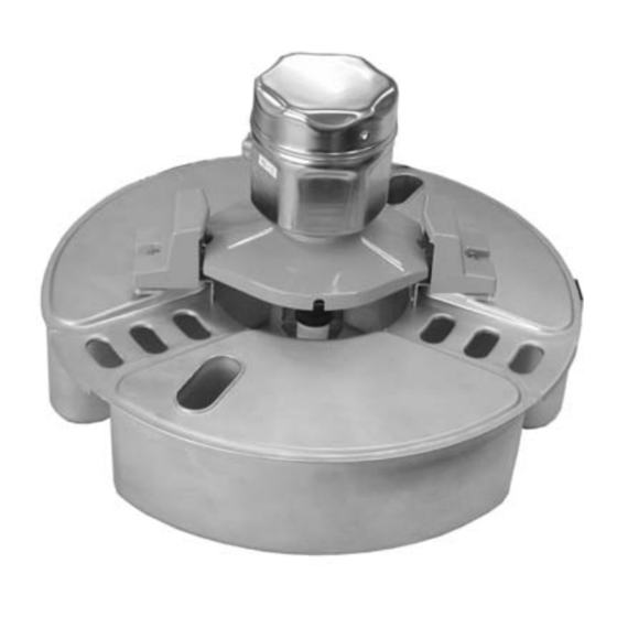
5.3.1 Handling precautions Always use both hands to hold the float when carrying NAR300. Do not lift or hold by any of the components shown in the figure below, and do not lift by the upper portion of the sensor. In addition, do not rotate the housing. Doing so may cause device failure. - Page 29 5.3.2 Float guide mounting NAR300 may be mounted on a float guide that has been installed for existing products (CFD10, CFD30, UFD10, NAR291, NAR292). If the float guide is shorter than 2 000 mm (78.74 in), either cut and use it or follow the protocol for when it is 2 000 mm (78.74 in) or longer and contact your Endress+Hauser...
- Page 30 Installation NAR300 system for high temperature 5.3.3 NAR300-x6xxxx and sensor I/F Ex box cable mounting Mounting procedure 1. Remove the intrinsically safe terminal box cover [5] and the circuit board guard [4]. 2. Insert the float sensor cable [2] into the cable gland [1] and cable entry of the intrinsically safe terminal box.
- Page 31 NAR300 system for high temperature Installation 5.3.4 NRR261-3/5xx cable mounting Mounting procedure 1. Remove the intrinsically safe terminal box cover [6] and the terminal block cover [5]. 2. Insert the float sensor cable [2] into the cable gland [1] and cable entry of the intrinsically safe terminal box.
-
Page 32: Adjustment
Installation NAR300 system for high temperature Adjustment 5.4.1 Verification of detection sensitivity in actual liquid Verification of detection sensitivity when the lower layer is water and the upper layer is oil If the electrode tip is pulled out of the lower-layer water due to increased thickness of the oil layer, water may cling onto the electrode tip like an icicle even if the electrode tip is in oil. -
Page 33: Electrical Connection
Connect the external grounding terminal according to the "Class A grounding" standards (≤ 10 Ω) in the shortest implementable distance. When using Ex [ia] float sensor NAR300 and Ex d [ia] transmitter NRR261, it is necessary to ground the NRR261 to a built-in safety barrier by following the procedure below (TIIS specifications only). -
Page 34: Nrr262-2/4/A/B/C Wiring
N.C COM N.O A0039908 22 Wiring of Ex [ia] transmitter NRR262-2/A/B/C Float sensor NAR300-x6xxxx (sensor I/F Ex box is also included in the code) Sensor I/F Ex box Ex [ia] transmitter NRR262 Green/Thread (M3) (see 1 below) Output to NRR262/Thread (M3) - Page 35 Although cable (1) that connects NAR300 and a sensor I/F Ex box is included with the device, a cable (2) that connects a sensor I/F Ex box and NRR262 is not included, and it must be prepared by the customer. For detailed information on the connection cables, see the "Process conditions"...
-
Page 36: Nrr261-3/5 Wiring
N.O1 A0039909 23 Wiring of Ex d [ia] transmitter NRR261-3 Float sensor NAR300-x6xxxx (sensor I/F Ex box is also included in the code) Sensor I/F Ex box Ex d [ia] transmitter NRR261 (separate type) Green/Thread (M3) (see 1 below) - Page 37 The cable (1) for connecting NAR300 and sensor I/F Ex box is included with NAR300. The cable (5) connecting the sensor I/F Ex box to the NRR261, the alarm output cable (2) from the NRR261, as well as the power cable (3) to the NRR261 are not included and must be prepared by the customer.
-
Page 38: Wiring Diagram
Electrical connection NAR300 system for high temperature Wiring diagram A0039910 24 Wiring diagram Ex d-type transmitter system (integrated type) Intrinsically safe-type transmitter system (separate type) Protection earth (protective grounding) GND Class A grounding (TIIS specifications only) Conductivity detection electrode (sensor) -
Page 39: Operating Principles Of Alarm Activation
Electrical connection Operating principles of alarm activation The oil leak detection signal detected by the NAR300 float sensor is converted to a power signal in the transmitter or the sensor I/F Ex box. After this, it is connected to the current detection circuit via the Ex [ia] safety barrier in the transmitter. -
Page 40: Troubleshooting
Troubleshooting NAR300 system for high temperature Troubleshooting Fail-safe (alarm is output when there is no oil leak) There is a risk of an alarm being output due to the following causes even if there is no actual oil leak. Item... -
Page 41: Operation Check
NAR300 system for high temperature Troubleshooting Operation check 7.3.1 Operation check flow diagram Start Remove the float Alarm sensor from pit and occurs in pit. clean the sensor. Remove H+ and H- Alarm occurs cables and confirm Transmitter failure a er returning sensor. - Page 42 Troubleshooting NAR300 system for high temperature Prior to performing an alarm operation check, take preemptive measures to ensure that the alarm system will not be impacted even if an oil leak alarm is activated. Refer to the previous section "Operation check flow diagram" for how to perform an operation check.
-
Page 43: Firmware History
7.3.3 Cleaning the conductive sensor unit Normally, NAR300 checks the conductivity state between the tip of the electrode and the main unit of the float. With conductivity, it determines that there is "water" and without conductivity, it determines that there is "oil or air." Since the electrode holder is connected to the main unit of the float, if the holder becomes conductive, it determines that "water"... -
Page 44: Maintenance
8.1.2 Periodic inspections While the NAR300 float sensor is not easily affected by deposits or adhered material, conduct overall periodic inspections of the cable and wiring, etc., semi-annually along with an operation check as follows. -
Page 45: Repair
General information on repairs 9.1.1 Repair concept The Endress+Hauser repair concept assumes that the devices have a modular design and that repairs can be done by the Endress+Hauser Service Department or specially trained customers. Spare parts are contained in suitable kits. They also come with relevant replacement instructions. -
Page 46: Return
Repair NAR300 system for high temperature Return The requirements for safe device return can vary depending on the device type and national legislation. 1. Refer to the website for more information: http://www.endress.com/support/return-material 2. Return the device if repairs or a factory calibration are required, or if the wrong device was ordered or delivered. -
Page 47: Accessories
NAR300 system for high temperature Accessories Accessories 10.1 Float guide If you ordered a device that is equipped with a float guide, install the float horizontally. Remove any debris or stones so that the float sensor can land horizontally. The standard length of a float guide is 2 m (6.57 in);... -
Page 48: U-Bolt/Cable Gland (Waterproof Connection)
Accessories NAR300 system for high temperature 10.2 U-bolt/cable gland (waterproof connection) The U-bolt (JIS F3022 B50) is used when mounting a transmitter. Have a spare 50A (2B φ60.5 mm (198.5 in)) pipe ready. Tighten and secure the cable gland after inserting the cable from NAR300. -
Page 49: Index
NAR300 system for high temperature Index Index Symbols Application ....... . . 7 Safety Instructions Basic . - Page 52 *71559868* 71559868 www.addresses.endress.com...
Need help?
Do you have a question about the NAR300 and is the answer not in the manual?
Questions and answers