
Related Manuals for Leviton 3300 series


Summary of Contents for Leviton 3300 series
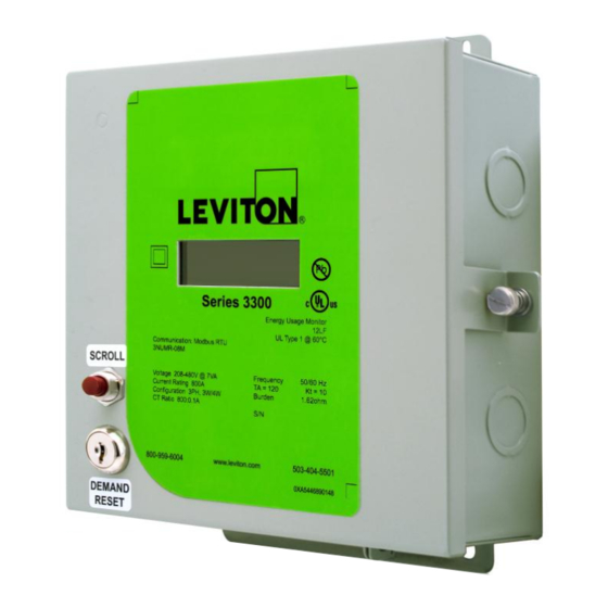
- Page 1 Series 3300 Multi-Function Meter with RS485 Communications Series 3500 Multi-Function Meter with Ethernet Communications Installation and User’s Manual Revision C 0XA6609-890000...
-
Page 2: Table Of Contents
4.5 Manually Setting the Real Time Clock ................23 5. Real Time Clock (RTC) Battery Replacement ................. 24 6. Communications – Series 3300 RS485 Communication Models ..........25 6.1 Modbus RTU Quick Start Guide ..................25 Leviton Manufacturing Co., Inc. Table of Contents... - Page 3 Percentage Registration: The ratio of the actual registration to the true value, expressed as a percent. Power-Active: The time average of the instantaneous power over one period of a wave, measured in Watts (W). Leviton Manufacturing Co., Inc. Table of Contents...
-
Page 4: Product Description
Communication Options: o RS485 Options (Series 3300) Modbus RTU BACnet MS/TP o Ethernet Options (Series 3500) Modbus TCP/IP BACnet o Isolated Pulse Outputs (10Wh and 1kWh), all models 10-year warranty Leviton Manufacturing Co., Inc. -
Page 5: Technical Specifications
08 = 800A U = Universal (208-480VAC) 16 = 1600A 30 = 3000A Communication Protocol 50 = 5000A MR = Modbus RTU (3300) BM = BACnet MS/TP (3300) MT = Modbus TCP or BACnet IP (3500) Leviton Manufacturing Co., Inc. -
Page 6: Serial Number Description
* For all 2PH Configurations hot legs must be landed on L1 and L2. 177-552 VAC Supply Voltage Range (Line 1 to Line 2) Maximum Input Power 10.2 VA Max. Primary: Max Rated Current + 10% Maximum Rated Current Secondary: 0.11 A Leviton Manufacturing Co., Inc. -
Page 7: I/O Connections And User Display
Current Transformers Inputs, Pulse and RS485 outputs Table 1: Series 3300/3500 electrical specifications Accuracy based on Leviton solid-core current transformers with 100 mA max output. Meter input burden resistance at 1.62 Ohms. Pollution Degree 2: Normally only non-conductive pollution occurs. Occasionally, however, a temporary conductivity caused by condensation must be expected. - Page 8 1k (+) Terminal 3 Real Energy (kWh) consumption (energy delivered) pulse output, plus (+) connection (collector of an NPN opto-isolated transistor). 10 Watthour (Wh) pulse rate (500 watthours on, 500 watthours off). VB = ?; I Max = ? Leviton Manufacturing Co., Inc.
-
Page 9: Installation Instructions
Series 3500 meters in an outdoor or outdoor enclosure. If technical assistance is required at any point during the installation, contact information can be found at the end of this manual. Leviton is not responsible for damage to the meter caused by incorrect wiring. 3.1. Explanation of Warning Symbols Indicates the need to consult the operation manual due to the presence of a potential risk. -
Page 10: Safety Precautions
Failure to follow these warnings could result in serious injury or death. Bonding kit must be UL recognized. Leviton recommends Rockwell Automation 855BM-ABK 3.3 Preparation 1. Verify the model number and electrical specifications of the device being installed to confirm they are appropriate for the intended electrical service (see Section 2). -
Page 11: List Of Materials
14 AWG wires recommended and 600VAC minimum rating required. Check local electrical code for compliance with regulations. List torque setting information. Current Transformers (CTs): This product is designed for use with Leviton CTs; see Section 3.7 for details. Conduit and fittings (see note 5 in Section 3.3). -
Page 12: Mounting Procedure And Conduit Installation
For outdoor enclosures UL Type 4X conduit and fittings must be used in order to maintain the outdoor rating of the enclosure. 4. Ensure conduit fittings are aligned properly and tightened securely to prevent moisture from entering the enclosure (outdoor applications). Leviton Manufacturing Co., Inc. - Page 13 Series 3300/3500 Installation and User‘s Manual Revision 0.9 Figure 3: Series 3300/3500 Indoor Steel Enclosure Dimensions, in Inches Leviton Manufacturing Co., Inc.
-
Page 14: Installation Of Voltage Lines
5. Connect additional in line fuses if required. 6. For connections to the Series 3300/3500 pulse outputs: Route wiring through the top of the enclosure. Strip wiring to approximately .300 inches and connect to the appropriate Leviton Manufacturing Co., Inc. -
Page 15: Variations And Installation Of Current Transformers
Splices on the CT leads must be within the meter enclosure, not inside the conduit. Leviton provided CT leads are 48 inches minimum. Wire insulation should be stripped so that the bare conductor length that connects to the meter terminal block does not exceed 0.300 inches. - Page 16 Revision 0.9 CT Variations Leviton solid core CTs (Figure 6, left photo): In accordance with CT label, the LINE side of CT must face incoming Line. White lead connects to the appropriate X2 terminal. Black or colored lead connects to the appropriate X1 terminal.
- Page 17 Hookup Diagrams, Figures 8 through 11 Series 3300/3500 Meter 3PH 4W Hookup IMPORTANT! H1, white side, white dot, or labeled side of CTs must face source (LINE) LOAD LINE Figure 8: 3-phase 4-wire Wye hookup diagram Leviton Manufacturing Co., Inc.
-
Page 18: Securing The Enclosure
CT connections at the meter may be reversed or connected to the wrong CT input terminals, or voltage wires at the meter could be cross-phased. Section 4 further describes how the Amperage screens operate to indicate a reverse energy Leviton Manufacturing Co., Inc. -
Page 19: General Metering Features And Functionality
4 seconds in the order shown in Table 4. To return to manual mode press and release the scroll button briefly (less than one second). Leviton Manufacturing Co., Inc. - Page 20 (A, B, or C) flash when Energy Flow arrow points left. When meter is installed in a mono-directional metering application, the Amps and kW arrows should always point to the right when load current is present. Leviton Manufacturing Co., Inc.
-
Page 21: Display Sequence And Screen Numbers
Serial Number. For example, a display showing ―03‖ on the left and ―6149‖ on the right below represents meter serial number XXXXXC6149, with the X‘s indicating the manufacturing day and year. See section 2.2 for more information on meter serial numbers. Leviton Manufacturing Co., Inc. -
Page 22: Descriptions Of Displayed Information
Modbus or BACnet Address 0004 (see Sections 6 and 7). In the event of a power loss Real Energy Delivered data will be saved in EEPROM and retained even if backup battery is depleted. The direction arrow always points to the right to indicate energy consumed (delivered). Leviton Manufacturing Co., Inc. - Page 23 (A, B, or C) flash when Energy Flow arrow points left. If meter is installed in a mono-directional application, the Amps and kW arrows should always point to the right when load current is present. Leviton Manufacturing Co., Inc.
-
Page 24: Manually Setting The Real Time Clock
7. The next KEYSWITCH ON/release cycle will show the Time and flash the Hour. 8. Repeat the setting sequence for Hour (0-23), Minutes (0-59) and Seconds (0-59). 9. You may again perform KEYSWITCH ON/Release to cycle back to the Date settings, if desired. Leviton Manufacturing Co., Inc. -
Page 25: Real Time Clock (Rtc) Battery Replacement
3. Grip the top metering board from both sides and pull to detach from the bottom board. 4. Remove the old battery from the coin slot with a pair of tweezers, noting the polarity. 5. Insert the new battery into the slot with the same polarity. Leviton Manufacturing Co., Inc. -
Page 26: Communications - Series 3300 Rs485 Communication Models
Figure 12: Metrology Cover Screws Metrology Cover Screws (4 places) 6. Communications – Series 3300 RS485 Communication Models 6.1 Modbus RTU Quick Start Guide Figure 13: RS485 Cable Entry Location Example of Communications Top Side Cable Entry Point Leviton Manufacturing Co., Inc. - Page 27 OFF position. Baud rate options are shown in Table 6. 6. Before energizing the meter close and secure the enclosure door. Table 6. Modbus RTU Baud Rate Switch Settings Switch Baud Rate Auto 9600 19200 38400 76800 Leviton Manufacturing Co., Inc.
- Page 28 Series 3300/3500 Installation and User‘s Manual Revision 0.9 Figure 14. Modbus RTU Connection Inverting (-) Non-Inverting (+) Signal Common (C) 5V DC Figure 15. Modbus RTU Switches Modbus Address Baud Rate Leviton Manufacturing Co., Inc.
-
Page 29: Bacnet Ms/Tp Quick Start Guide
6. Before energizing the meter close and secure the enclosure door. Note: For detail information refer to FieldServer Website: www.fieldserver.com Table 7. BACnet MS/TP Baud Rate Switch Settings Switch Baud Rate Auto 1200 2400 4800 9600 19200 20833 28800 38400 57600 76800 115200 Leviton Manufacturing Co., Inc. -
Page 30: Communications - Series 3500 Ethernet Models
To reduce risk of electric shock, always open or disconnect the circuit from the power distribution system of a building before servicing an electric meter. Use a properly rated voltage sensing device to confirm power is off. Leviton Manufacturing Co., Inc. -
Page 31: Communications - History Data Extraction
Modbus address 83 regardless of the meter’s normal Modbus address configuration. For diagnostic purposes, history data can be extracted from the meter using a Modbus RTU connection to the meter base unit. This feature is intended for trained field service personnel only. Contact Leviton Customer Support for assistance. -
Page 32: Data Extraction Procedure
The control options for the date and the number of profiles are made available in registers Leviton Manufacturing Co., Inc. - Page 33 Once the desired number of readings has been found and transferred the transmission ends. Historical Data Profile Structure The historical data is transmitted in frames consisting of 48 bytes each. The frame structure is shown in Table 9. Leviton Manufacturing Co., Inc.
- Page 34 Time of use Year Time of use Month Time of use Day Time of use Hour Time of use Minute Time of use Second Phase A Voltage Phase A Voltage Phase A Voltage Phase A Current Phase B Current Leviton Manufacturing Co., Inc.
- Page 35 Once one frame is finished transmitting, the next frame will begin automatically until the number of profiles left to send reaches zero. History data is transmitted in reverse chronological order—the most recent frame is transmitted first and the oldest frame is transmitted last. Leviton Manufacturing Co., Inc.
-
Page 36: Series 3300/3500 Pulse Outputs
Both pulse outputs are electrically isolated from input power and can be used independent of one another or simultaneously. 4. Before energizing the meter close and secure the enclosure door. Figure 18. Pulse Output Connections 10 Wh/P COM 1 kWh/P Leviton Manufacturing Co., Inc. -
Page 37: Connecting Pulse Outputs To Data Acquisition Equipment
9.2 Connecting Pulse Outputs to Data Acquisition Equipment. A variety of data acquisition equipment may be connected to the Series 3300/3500 pulse output terminals, included wireless pulse transceivers and data logging equipment. For information on Leviton‘s complete line of data acquisition products go to Leviton.com >Products>Submetering>Communication Systems. -
Page 38: Diagnostic Tools And Frequently Asked Questions
Power Factor values should be between -0.5 and +0.5. An absolute value less than 0.5 indicates CTs installed on the wrong phase or backwards. Recheck wiring and CT orientations against the appropriate Hookup Diagram shown in Figures 8 through 11. Leviton Manufacturing Co., Inc. -
Page 39: Frequently Asked Questions
A: Industry convention for color coding in 3 Phase 208V electrical systems assigns the color black to phase A, red to phase B, Blue to phase C, and white to Neutral. Leviton‘s 100A and 200A solid core CTs are coded with the same colors (on the body of the CTs and on the wires) to help installers get each CT placed on the correct hot leg. -
Page 40: Returned Material Policy And Warranty Information
3. Original purchase order number 4. Reason for return All paperwork and boxes must be marked with an RMA number issued by Leviton. All authorized returned materials must be shipped freight prepaid to Leviton to the address specified below. Leviton is not responsible for uninsured packages or packages lost by your carrier. -
Page 41: Contact Information
Leviton S. de R.L. de C.V. Lago Tana 43, Mexico DF, Mexico CP 11290 • Tel. (+52) 55-5082-1040 • www.leviton.com.mx Visit our Website at www.leviton.com/les © 2012 Leviton Manufacturing Co., Inc. All rights reserved. Subject to change without notice. Leviton Manufacturing Co., Inc. -
Page 42: Appendix A
Phase A Apparent Power FLOAT32 0036 0024 40037 Phase B Apparent Power FLOAT32 0038 0026 40039 Phase C Apparent Power FLOAT32 0040 0028 40041 Phase A Reactive Power kVAR FLOAT32 0042 002A 40043 Phase B Reactive Power kVAR FLOAT32 Leviton Manufacturing Co., Inc. - Page 43 48 & 49 8-bit enumerated in 0071 0047 40072 RTC Day of the Week Net kWh ("from grid" minus "to 0072 0048 40073 grid") FLOAT32 Net kVAh ("from grid" minus "to 0074 004A 40075 grid") kVAh FLOAT32 Leviton Manufacturing Co., Inc.
- Page 44 Register address 5005 is encoded as two 8-bit enumerated values, with demand calculation interval in the MSB and history data save interval in the LSB. Demand interval (MSB) defines the interval for calculation of maximum demand: Leviton Manufacturing Co., Inc.
- Page 45 LSB and the history data save interval is fixed at 5 minutes and cannot be changed. For all other protocols, the demand calculation interval value is written to the MSB and the history data save interval value is written to the LSB. Leviton Manufacturing Co., Inc.
-
Page 46: Appendix B
Series 3300/3500 Installation and User‘s Manual Revision 0.9 Appendix B S3300 meters support an RS-485 communication network and meters can be daisy-chained up to 32 units. A connection example is shown below. Leviton Manufacturing Co., Inc. -
Page 47: Appendix C
Series 3300/3500 Installation and User‘s Manual Revision 0.9 Appendix C How to Set Up Leviton Modbus RTU Communication Modules Communication Module Jumpers To use the Modbus RTU communication module the jumpers shown above must be set in the top position, which is the default setting from factory. The jumpers must be set as shown in the diagram above regardless of the communication protocol in use. - Page 48 Zero (all switches off) is not a valid Modbus address. The address 255 (all switches on) is generally reserved and not recommended. The table below shows how to set the switches for each address. Leviton Manufacturing Co., Inc.
- Page 49 Series 3300/3500 Installation and User‘s Manual Revision 0.9 Leviton Manufacturing Co., Inc.
- Page 50 Series 3300/3500 Installation and User‘s Manual Revision 0.9 Leviton Manufacturing Co., Inc.
- Page 51 Series 3300/3500 Installation and User‘s Manual Revision 0.9 Leviton Manufacturing Co., Inc.
Need help?
Do you have a question about the 3300 series and is the answer not in the manual?
Questions and answers