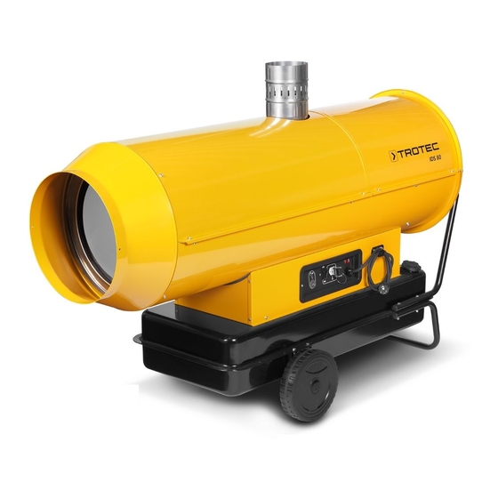
Trotec IDS 80 Operation Manual
Oil heater
Hide thumbs
Also See for IDS 80:
- User manual (80 pages) ,
- Operating manual (80 pages) ,
- Original instructions manual (27 pages)
Table of Contents
Advertisement
Quick Links
Advertisement
Table of Contents

Summary of Contents for Trotec IDS 80
- Page 1 IDS 45 / 80 OPERATION MANUAL OIL HEATER...
-
Page 2: Table Of Contents
Circuit diagram IDS 45......9 Support bracket for axis Circuit diagram IDS 80......A-10 Setting of the air setting ring . -
Page 3: General Safety Instructions
The oil heating unit IDS 45 and/or IDS 80 is used to heat up room air in order to achieve a fast heating of large rooms. Risk of explosion! The oil heating unit is operated with heating oil. -
Page 4: Fuels
Proper use 9. Description of device The oil heating unit IDS 45 and/or IDS 80 has been developed for the gen- eration of hot air and may be used indoors and in roofed outdoor areas. The oil heating unit IDS 45 and/or IDS 80 consists of the following com-... -
Page 5: Installation And Commissioning
10. Installation and commissioning • Check that the scope of delivery of your oil heating unit is com- plete. If an accessory part is missing, please contact the Trotec customer service or the specialist dealer from whom you pur- chased the device. -
Page 6: Switching Off The Oil Heating Unit
• Switch the device on by setting the selector switch to the position • continuous red light for safety shutdown of the device "ON" (continuous operation). • flashing orange light if the operation is interrupted due to consid- 2. Automatic mode erable mains fluctuations (T <... -
Page 7: Care And Maintenance
• Dismount the burner and clean its components using a brass Please contact: brush. Trotec GmbH Co KG • Clean the electrodes. Check the distance of the electrodes and adjust it if required (see figure). Grebbener Straße 7 D-52525 Heinsberg Tel.: 49 (0) 2452 / 962 - 400... - Page 8 Problem Reset button Cause Error correction Operation indi- Self-diagnostic cator indicator Fan does not start run- switched off Control device is incor- - Check if the control equipment is correctly set ning and flame is not rectly set (e.g. the temperature set at the thermostat must ignited be higher than the room temperature).
- Page 9 Problem Reset button Cause Error correction Operation indi- Self-diagnostic cator indicator Solenoid valve defective Contact the customer service in order to: - have the electrical connections checked. - have the safety thermostat LI checked. - have the solenoid valve cleaned or replaced. continuous Internal error of the elec- Contact the customer service in order to:...
-
Page 10: Appendix
18. Appendix Circuit diagram IDS 45 Control unit FO Photoelectric cell Thermostat connection CO Capacitor Indicator lamp MV Fan motor LI 1 Safety thermostat FUA Fuse EV 1 Solenoid valve FU Fuse Relay RV Selector switch RFI filter Ignition transformer Heated filter (optional) Operating manual –... -
Page 11: Circuit Diagram Ids 80
Circuit diagram IDS 80 Control unit FO Photoelectric cell Thermostat connection CO Capacitor Indicator lamp MV Fan motor LI 1 Safety thermostat FUA Fuse EV 1 Solenoid valve FU Fuse Relay RV Selector switch RFI filter Ignition transformer Heated filter (optional) B-10 Operating manual –... -
Page 12: Setting Of The Air Setting Ring
Setting of the air setting ring Type IDS 45 Type IDS 80 Parameter Value Value Setting of air setting ring Operating manual – IDS 45 / 80 B-11... - Page 16 Trotec GmbH & Co. KG Grebbener Str. 7 D-52525 Heinsberg +49 2452 962-400 +49 2452 962-200 info @ trotec.com www.trotec.com...


Need help?
Do you have a question about the IDS 80 and is the answer not in the manual?
Questions and answers