
Related Manuals for Avigilon 1.3L-H3-B3


Summary of Contents for Avigilon 1.3L-H3-B3
- Page 1 Installation Guide Avigilon™ High Definition H.264 IP Camera Models: 1.0-H3-B1, 1.0-H3-B2, 1.0-H3-B3, 1.3L-H3-B2, 1.3L-H3-B3, 2.0-H3- B1, 2.0-H3-B2, 2.0-H3-B3, 3.0W-H3-B2, 3.0W-H3-B3, 5.0-H3-B2 and 5.0-H3-B3...
- Page 2 Power Source” with output rated 12 VDC or 24 VAC, 6 W min. or Power over Ethernet (PoE), rated 48 VDC, 6 W min. Any external power supply connected to this product may only be connected to another Avigilon product of the same model series. External power connections must be properly insulated.
- Page 3 Connect the equipment into an outlet on a circuit different from that to which the receiver is connected. Consult the dealer or an experienced radio/TV technician for help. Changes or modifications made to this equipment not expressly approved by Avigilon Corporation or parties authorized by Avigilon Corporation could void the user’s authority to operate this equipment.
- Page 4 Legal Notices © 2012 -2015 Avigilon Corporation. All rights reserved. Unless expressly granted in writing, no license is granted with respect to any copyright, industrial design, trademark, patent or other intellectual property rights of Avigilon Corporation or its licensors.
-
Page 5: Table Of Contents
Table of Contents Overview Front View Rear View Installation Required Tools and Materials Camera Package Contents Installation Steps Mounting the Camera Connecting Cables Assigning an IP Address Accessing the Live Video Stream Aiming and Focusing the Camera (Optional) Configuring Onboard Storage For More Information Cable Connections Connecting External Power... -
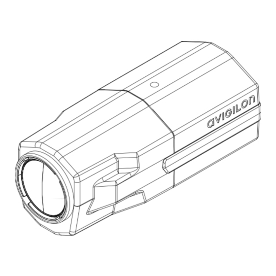
Page 6: Overview
Overview Front View 1. Camera Mounts Provides mounting points for the camera. Mounts accept 1/4”-20 UNC bolts commonly found on tripods and mounting brackets. 2. Serial Number Tag Product serial number and part number label. Overview... -
Page 7: Rear View
Rear View 1. I/O Connector Block Provides connections to external input/output devices. 2. Audio/Video Connector Accepts a mini-jack connector (3.5 mm). 3. Link LED Indicates if there is an active connection in the Ethernet port. 4. Connection Status LED Provides information about device operation. For more information, see LED Indicators on page 10 5. - Page 8 7. SD Card Slot Accepts an SD card for onboard storage. Rear View...
-
Page 9: Installation
Small slotted screwdriver with 5/64” or 2 mm blade width — for connecting power when not using Power over Ethernet. Mounting bracket, enclosure or tripod. Camera Package Contents Avigilon™ High Definition IP Camera Terminal block Installation Steps Complete the following steps to install the device:... -
Page 10: Assigning An Ip Address
NOTE: The default camera username is admin and the default camera password is admin. Aiming and Focusing the Camera Use the Avigilon Camera Installation Tool or camera web browser interface to aim and focus the camera. Consult the software user guide for more information. -
Page 11: (Optional) Configuring Onboard Storage
The SD card can only be inserted in the orientation shown on the camera. 2. Access the camera’s web interface to enable the onboard storage feature. For more information, see the Avigilon High Definition H.264 Camera Web Interface User Guide. For More Information Additional information about setting up and using the device is available in the following guides: Avigilon™... -
Page 12: Cable Connections
Cable Connections Connecting External Power NOTE: Do not perform this procedure if Power over Ethernet (POE) is used. If PoE is not available, the device needs to be powered through the removable power connector block. Refer to the diagrams in this guide for the location of the power connector block. The device can be powered from 12 VDC or 24 VAC. -
Page 13: Connecting To Microphones, Speakers And Video Monitors
1. Ground 2. Input — To activate, connect the Input to the Ground pin. To deactivate, leave disconnected or apply between 3-15 V. 3. Output — When active, Output is internally connected with the Ground pin. Circuit is open when inactive. Maximum load is 25 VDC, 120 mA. - Page 14 Figure 1: Mini-jack audio video connector 1. Audio IN 2. Composite Video OUT 3. GND 4. Audio OUT Connecting to Microphones, Speakers and Video Monitors...
-
Page 15: Led Indicators
LED Indicators Once connected to the network, the Connection Status LED will display the progress in connecting to the Network Video Management software. The following table describes what the LEDs indicate: Connection Status Connection State Description One short flash every Obtaining IP Address Attempting to obtain an IP address. -
Page 16: Resetting To Factory Default Settings
Resetting to Factory Default Settings If the camera no longer functions as expected, you can choose to reset the camera to its factory default settings. Use the firmware revert button to reset the camera. Figure 2: The firmware revert button on the rear of the camera 1. -
Page 17: Setting The Ip Address Using The Arp/Ping Method
Setting the IP Address Using the ARP/Ping Method Complete the following steps to configure the camera to use a specific IP address: 1. Locate and copy down the MAC Address (MAC) listed on the Serial Number Tag for reference. 2. Open a Command Prompt window and enter the following commands: a. -
Page 18: Specifications
Specifications Camera Audio Input Line input, A/V mini-jack (3.5 mm) Video Output NTSC/PAL, A/V mini-jack (3.5 mm) H3-B1: 4.7-84.6mm, F1.6, P-iris Lens H3-B2: 3-9mm, F1.2, P-iris H3-B3: 9-22mm, F1.6, P-Iris Onboard Storage SD/SDHC/SDXC slot – minimum class 4; class 6 or better recommended Network Network 100Base-TX... - Page 19 Operating -10 °C to +50 °C (14 °F to 122 °F) Temperature Storage -10 °C to +70 °C (14 °F to 158 °F) Temperature Humidity 0-95% non-condensing Certifications UL 60950 CSA 60950 EN 60950-1 Safety WEEE ROHS FCC Part 15 Subpart B Class B Electromagnetic EN 55022 Class B Emissions...
-
Page 20: Limited Warranty & Technical Support
Limited Warranty & Technical Support Avigilon warrants to the original consumer purchaser, that this product will be free of defects in material and workmanship for a period of 3 years from date of purchase. The manufacturer’s liability hereunder is limited to replacement of the product, repair of the product or replacement of the product with repaired product at the discretion of the manufacturer.
Need help?
Do you have a question about the 1.3L-H3-B3 and is the answer not in the manual?
Questions and answers