Avigilon 1.0W-H3PTZ-DP20 Installation Manual
High definition h.264 ptz ip dome camera
Hide thumbs
Also See for 1.0W-H3PTZ-DP20:
- Installation manual (145 pages) ,
- Web interface user manual (28 pages) ,
- Installation manual (24 pages)

Related Manuals for Avigilon 1.0W-H3PTZ-DP20


Summary of Contents for Avigilon 1.0W-H3PTZ-DP20
-
Page 1: Installation Guide
Installation Guide Avigilon™ High Definition H.264 PTZ IP Dome Camera Models: 1.0W-H3PTZ-DP20 and 2.0W-H3PTZ-DP20... - Page 2 Ethernet (PoE) Plus IEEE802.3at Type 2 compliant Power Sourcing Equipment (PSE) rated 42.5-57 VDC, 25.5W min. Any external power supply connected to this product may only be connected to another Avigilon product of the same model series. External power connections must be properly insulated.
-
Page 3: Fcc Notice
Connect the equipment into an outlet on a circuit different from that to which the receiver is connected. Consult the dealer or an experienced radio/TV technician for help. Changes or modifications made to this equipment not expressly approved by Avigilon Corporation or parties authorized by Avigilon Corporation could void the user’s authority to operate this equipment. -
Page 4: Legal Notices
Avigilon Corporation protects its innovations with patents issued in the United States of America and other jurisdictions worldwide (see avigilon.com/patents). Unless stated explicitly and in writing, no license is granted with respect to any copyright, industrial design, trademark, patent or other intellectual property rights of Avigilon Corporation or its licensors. - Page 5 Table of Contents Overview Front View Top View Pendant Mount Adapter Installation Camera Package Contents Installation Steps Removing Protective Material Inside Dome Cover Installing the Mount Adapter Connecting Cables Securing the PTZ Dome Camera Assigning an IP Address Accessing the Live Video Stream For More Information Cable Connections Connecting External Power...
-
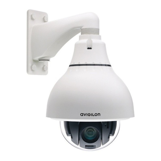
Page 6: Overview
Overview Front View 1. Serial number tag Device information, product serial number and part number label. 2. Connection status LED Provides information about device operation. For more information, see Connection Status LED Indicators on page 13. 3. Link LED Indicates if there is an active connection in the Ethernet port. Overview... -
Page 7: Top View
Top View 1. External power Accepts an external power connection when Power over Ethernet is not available or operation below -30 °C is required. 2. Lanyard anchor The safety lanyard attaches to the anchor to prevent the camera from falling during installation. 3. -
Page 8: Pendant Mount Adapter
Pendant Mount Adapter 1. 1-1/2” NPT mount adapter Standard 1-1/2” NPT adapter for mounting the dome camera to a pendant mount bracket. 2. Tamper resistant screws Torx captive screws to fix the dome camera to the mounting adapter. Pendant Mount Adapter... -
Page 9: Installation
Installation Camera Package Contents Ensure the package contains the following: Avigilon™ High Definition PTZ Dome Camera H3-MH-NPTA1 kit: 1 ½” NPT Adapter CAM-ACCS-H3PTZ kit: T20 Torx key Teflon Sealing Tape RJ-45 crimp-on plug and weather-resistant housing External Power wiring harness... - Page 10 1. Remove the dome cover by loosening the screws that fix the cover to the base. Use the T20 Torx key provided in the camera package. NOTE: Be careful not to scratch or touch the dome bubble. The resulting marks or fingerprints may affect the overall image quality.
-
Page 11: Installing The Mount Adapter
3. Attach the dome cover back to the base and tighten the screws. Installing the Mount Adapter CAUTION — The dome camera must be mounted as instructed below or problems with moisture may arise and will not be covered by the dome camera warranty. The dome camera must be mounted on a 1-1/2”... - Page 12 2. Pull the required cables through the mounting bracket then install the supplied connectors and wire assemblies. 3. Install the 1 1/2” NPT mount adapter. 4. Connect the safety lanyard from inside the NPT mount adapter to the anchor on the PTZ dome camera. Installing the Mount Adapter...
-
Page 13: Connecting Cables
Connecting Cables Refer to the diagrams in the Overview section for the location of the different connectors. To connect the cables required for proper operation, complete the following: 1. Make sure the safety lanyard is connected to the PTZ dome camera. 2. -
Page 14: Assigning An Ip Address
The IP address settings can be changed using one of the following methods: Camera's web browser interface: http://<camera IP address>/ Network video management software application (for example, Avigilon Control Center (ACC)™ software). ARP/Ping method. For more information, see Setting the IP Address Using the ARP/Ping Method on page 15. -
Page 15: Cable Connections
Cable Connections Connecting External Power NOTE: This procedure is not required if Power over Ethernet (PoE) is used. If PoE is not available or operation below -30 °C is required, the dome camera can be powered with 24 V AC or 24 V DC through the removable power connector: 1. - Page 16 Figure 1: Example application. 1. Dark Red — +12 VDC, 50 mA max. output for relay drive 2. Grey — Relay ground return 3. Red — Relay input 1 4. Orange — Relay input 2 5. Pink — Relay output 1 6.
- Page 17 The video output signal is determined by the camera flicker control setting. When the camera flicker control is set to 60 Hz, the video output signal is NTSC. When the flicker control is set to 50 Hz, the video output signal is PAL.
-
Page 18: Connection Status Led Indicators
Connection Status LED Indicators Once connected to the network, the Connection Status LED will display the progress in connecting to the Network Video Management software. The following table describes what the LEDs indicate: Connection Status Connection State Description One short flash every Obtaining IP Address Attempting to obtain an IP address. -
Page 19: Resetting To Factory Default Settings
Resetting to Factory Default Settings If the deviceno longer functions as expected, you can choose to reset the device to its factory default settings. Use the firmware revert button to reset the device. The firmware revert button is shown in the following diagram: NOTE: Be careful not to scratch the dome bubble. -
Page 20: Setting The Ip Address Using The Arp/Ping Method
Setting the IP Address Using the ARP/Ping Method Complete the following steps to configure the camera to use a specific IP address: 1. Locate and copy down the MAC Address (MAC) listed on the Serial Number Tag for reference. 2. Open a Command Prompt window and enter the following commands: a. -
Page 21: Cleaning
Cleaning Dome Bubble If the video image becomes blurry or smudged in areas, it may be because the dome bubble requires cleaning. To clean the dome bubble: Use hand soap or a non-abrasive detergent to wash off dirt or fingerprints. Use a microfiber cloth or non-abrasive fabric to dry the dome bubble. -
Page 22: Specifications
Specifications Camera Lens 4.7-94mm, 20x zoom, F1.6 and automatic focus Audio Input/Output Line level input and output Video Output NTSC/PAL Network Network 100Base-TX Cabling Type CAT5 Connector RJ-45 ONVIF compliance version 1.02, 2.00, Profile S (www.onvif.org) Password protection, HTTPS encryption, digest authentication, WS authentication, user Security access log, 802.1x port based authentication. - Page 23 Temperature -45 °C to + 50 °C (-50 °F to 122 °F) with external power Storage -10 °C to +70 °C (14 °F to 158 °F) Temperature Humidity 0-95% non-condensing Certifications ROHS Certifications WEEE UL 60950-1 Safety CSA 60950-1 IEC/EN 60950-1 IK10 Impact Rating Environmental IEC 60529 IP66 Rating...
-
Page 24: Limited Warranty And Technical Support
Limited Warranty and Technical Support Avigilon warranty terms for this product is provided at avigilon.com/warranty. Warranty service and technical support can be obtained by contacting Avigilon Technical Support: avigilon.com/contact-us/. Limited Warranty and Technical Support...
Need help?
Do you have a question about the 1.0W-H3PTZ-DP20 and is the answer not in the manual?
Questions and answers