
Related Manuals for Avigilon 1.3C-H4SL-BO1-IR


Summary of Contents for Avigilon 1.3C-H4SL-BO1-IR
-
Page 1: Installation Guide
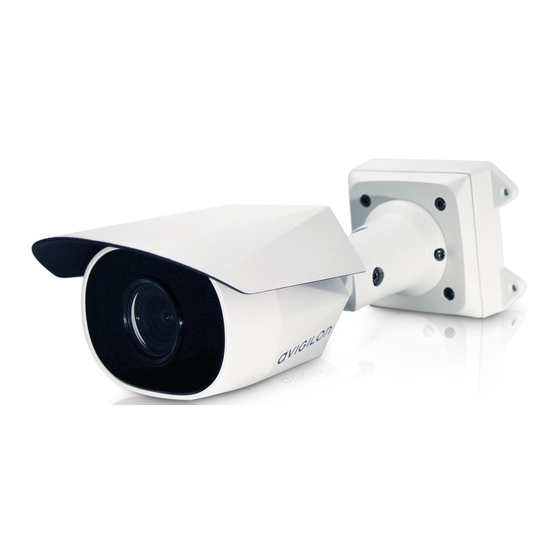
Installation Guide Avigilon H4 SL Bullet Camera Models: 1.3C-H4SL-BO1-IR, 2.0C-H4SL-BO1-IR and 3.0C-H4SL-BO1-IR... - Page 2 This product is intended to be supplied by Power over Ethernet (PoE) that is a “Limited Power Source” or “LPS”, rated 48 VDC, 9W min. Any external power supply connected to this product may only be connected to another Avigilon product of the same model series. External power connections must be properly insulated.
-
Page 3: Fcc Notice
The absence of the symbols ™ and ® in proximity to each trademark in this document is not a disclaimer of ownership of the related trademark. Avigilon Corporation protects its innovations with patents issued in the United States of America and other jurisdictions worldwide: avigilon.com/patents. - Page 4 Avigilon Corporation reserves the right to make any such changes without notice. Neither Avigilon Corporation nor any of its affiliated companies: (1) guarantees the completeness or accuracy of the information contained in this document; or (2) is responsible for your use of, or reliance on, the information.
-
Page 5: Table Of Contents
Table of Contents Overview Mounting Bracket View Rear View Front View Configuration Panel View Side View Installation Camera Package Contents Precautions for Installing Near Salt Water Installation Steps Mounting the Bullet Camera Removing the Configuration Panel Cover (Optional) Using the USB Wi-Fi Adapter Assigning an IP Address Accessing the Live Video Stream Aiming the Camera... -
Page 6: Overview
Overview Mounting Bracket View 1. Camera mounts Points for installing the camera to the mounting bracket. 2. Mounting hook slots Points to hold the camera to the mounting bracket while connecting the required cables. 3. Mounting holes Holes for securing the mounting bracket to the mounting surface. Overview... -
Page 7: Rear View
Rear View 1. Ethernet port Accepts power and Ethernet connection to the network. The camera can only be powered by Power over Ethernet (PoE). Server communication and image data transmission also occur over this connection. 2. Serial number tag Device information, product serial number and part number label. 3. -
Page 8: Front View
Front View 1. IR illuminator Provides scene illumination in the IR spectrum. 2. Configuration panel cover Covers the configuration panel. Front View... -
Page 9: Configuration Panel View
Accepts a microSD card for onboard storage. 2. Micro USB port Accepts a micro USB to USB adapter. Only required when using the Avigilon USB Wi-Fi Adapter. 3. Link LED Indicates if there is an active connection in the Ethernet port. -
Page 10: Side View
Side View 1. Sun shroud An adjustable cover to help protect the lens against glare from the sun. 2. Mount arm Adjustable mount arm for positioning the camera. 3. Adjustment screws Provides a locking mechanism for the mount arm. Side View... -
Page 11: Installation
Follow these precautions to avoid camera issues when installing in a salt heavy environment: Use mounting accessories offered by Avigilon. All Avigilon accessories are tested to work with Avigilon cameras in the rated environments. -
Page 12: Mounting The Bullet Camera
Mounting the Bullet Camera If the cables for the camera will not be provided from inside the mounting surface, install the junction box first (H4-BO-JBOX). After you install the junction box, you can skip directly to step 3 of this procedure. 1. - Page 13 4. Insert the mounting hooks on the rear of the camera into the mounting hook slots on the mounting bracket, then let the camera hang. 5. Install the protective cable boot. You may choose to skip this step if you are using the optional junction box.
- Page 14 6. Connect the cable to the camera's Ethernet port. 7. Tuck the extra lengths of cables into the cable entry hole. 8. Raise the camera until it covers the mounting bracket. Mounting the Bullet Camera...
-
Page 15: Removing The Configuration Panel Cover
For more information about configuring the camera from the mobile web interface see Avigilon USB Wi-Fi Adapter System User Guide. NOTE: The camera will reserve the 10.11.22.32/28 subnet for internal use while the USB Wi-Fi Adapter is plugged in. -
Page 16: Assigning An Ip Address
Wi-Fi Adapter on the previous page. Camera's web browser interface: http://<camera IP address>/. Network Video Management software application (for example, the Avigilon Control Center™ software). ARP/Ping method. For more information, see Setting the IP Address Using the ARP/Ping Method on page 17. - Page 17 1. Loosen the adjustment screw closest to the mounting bracket to rotate the camera arm. 2. Loosen the center adjustment screw to tilt the camera. 3. Loosen the adjustment screw on the camera to turn the camera body. Aiming the Camera...
-
Page 18: (Optional) Configuring Microsd Card Storage
For more information, see the Avigilon Camera Configuration Tool User Guide. If the camera is connected to the Avigilon Control Center system, you can use the client software to configure the camera. For more information, see the Avigilon Control Center Client User Guide. - Page 19 Avigilon Control Center Client User Guide Avigilon High Definition H.264 Web Interface User Guide Avigilon Camera Configuration Tool User Guide The manuals are available on the Avigilon website: avigilon.com/support-and-downloads. For More Information...
-
Page 20: Led Indicators
LED Indicators Once connected to the network, the Connection Status LED will display the progress in connecting to the Network Video Management software. The following table describes what the LEDs indicate: Connection Status Connection State Description One short flash every Obtaining IP Address Attempting to obtain an IP address. -
Page 21: Resetting To Factory Default Settings
Resetting to Factory Default Settings If the camera no longer functions as expected, you can choose to reset the camera to its factory default settings. Use the firmware revert button to reset the camera. The firmware revert button is shown in the following diagram: Figure 1: The firmware revert button in the Configuration Panel. -
Page 22: Setting The Ip Address Using The Arp/Ping Method
NOTE: The ARP/Ping Method will not work if the Disable setting static IP address through ARP/Ping method check box is selected in the camera's web browser interface. For more information, see the Avigilon™ High Definition H.264 Web Interface User Guide. -
Page 23: Specifications
Specifications Camera Lens 3-9 mm, motorized, varifocal USB Port USB 2.0 microSD/microSDHC/microSDXC slot – minimum class 6; class 10/UHS-1 or better SD Storage recommended Network Network 100Base-TX Cabling Type CAT5 Connector RJ-45 ONVIF ONVIF® compliance version 1.02, 2.00, Profile S (www.onvif.org) Device Management SNMP v2c Protocols... - Page 24 Humidity 0-95% non-condensing Certifications ROHS Certifications WEEE UL 60950-1 CSA 60950-1 Safety IEC/EN 60950-1 IEC 62471 IK10 Impact Rating Environmental Meets IEC 60529 IP66 Weather Rating IEC/UL/CSA 60950-22 FCC Part 15 Subpart B Class B EN 55022 Class B EN 55032 Electromagnetic IC ICES-003 Class B Emissions...
-
Page 25: Limited Warranty And Technical Support
Limited Warranty and Technical Support Avigilon warranty terms for this product is provided at avigilon.com/warranty. Warranty service and technical support can be obtained by contacting Avigilon Technical Support: avigilon.com/contact-us/. Limited Warranty and Technical Support...
Need help?
Do you have a question about the 1.3C-H4SL-BO1-IR and is the answer not in the manual?
Questions and answers