Table of Contents
Advertisement
Quick Links
Reference Manual
P VD 5660 D
P VD 5660 B
Dual Channel SD/HD Multi-rate Frame Synchronizer with Full
Embedded and External AES Audio Support
This Manual Supports Device Revisions:
P VD 5660 Firmware Revision
Control System GUI Release
Information in this document is subject to change without notice. No part of this document may be reproduced or
transmitted in any form or by any means, electronic or mechanical for any purpose, without express written permission of
LYNX Technik AG may have patents, patent applications, trademarks, copyrights or other intellectual property rights
covering the subject matter in this document. Except as expressly written by LYNX Technik AG, the furnishing of this
document does not give you any license to patents, trademarks, copyrights or other intellectual property of LYNX Technik
Revision 1.3 - October 2008
LYNX Technik AG.
AG or any of its affiliates.
LYNX Technik AG
Brunnenweg 3
D 64331 Weiterstadt
Germany
www.lynx-technik.com
© 2008 LYNX Technik AG all rights reserved
275
4.4.0
Advertisement
Table of Contents

Subscribe to Our Youtube Channel
Related Manuals for Lynx P VD 5660 D


Summary of Contents for Lynx P VD 5660 D
- Page 1 LYNX Technik AG may have patents, patent applications, trademarks, copyrights or other intellectual property rights covering the subject matter in this document. Except as expressly written by LYNX Technik AG, the furnishing of this document does not give you any license to patents, trademarks, copyrights or other intellectual property of LYNX Technik AG or any of its affiliates.
-
Page 2: Table Of Contents
P VD 5660 Reference Manual. Rev 1.3 Contents WARRANTY............................ 5 REGULATORY INFORMATION ..................... 6 Europe............................6 Declaration of Conformity ....................... 6 USA 6 FCC 47 Part 15 ........................6 GETTING STARTED........................7 Packaging............................ 7 ESD Warning..........................7 Preventing ESD Damage......................7 PRODUCT DESCRIPTION ...................... - Page 3 P VD 5660 Reference Manual. Rev 1.3 FIRMWARE OPTIONS........................21 Second Input Option (OC-5660-SCND) ..................21 User Setting with GPI Control (OC-5660-USET) ..............21 Metadata Option (OC-5660-META) ..................21 Down Conversion Option (OC-5660-DWN) ................22 4:3 Letterbox ......................... 22 4:3 Center Cut........................22 4:3 Stretch to Fill ........................
- Page 4 P VD 5660 Reference Manual. Rev 1.3 Color Space Conversion ....................... 34 Aperture Correction....................... 35 H and V Blanking ........................35 Video Delay Adjustment......................35 Settings ..........................35 Freeze Mode......................... 35 Test Pattern Pre-select ......................36 Test Pattern Standard......................36 Test Pattern Enable ......................
-
Page 5: Warranty
LYNX Technik supplies; or d) to service a product which has been modified or integrated with other products when the effect of such modification or integration increases the time or difficulty servicing the product. -
Page 6: Regulatory Information
Brunnenweg 3 D-64331 Weiterstadt Germany Declare under our sole responsibility that the product TYPE: P VD 5660 B, P VD 5660 D To which this declaration relates is in conformity with the following standards (environments E1-E3): EN 55103-1 /1996 EN 55103-2 /1996 EN 60950 /2001 Following the provisions of 89/336/EEC and 73/23/EEC directives. -
Page 7: Getting Started
P VD 5660 Reference Manual. Rev 1.3 Getting Started Most CardModules are installed into the rack frames and system tested in the factory. If this is an upgrade part or service exchange item then the module is supplied in a padded cardboard carton which includes the CardModule, rear connection plate and mounting screws. -
Page 8: Product Description
P VD 5660 Reference Manual. Rev 1.3 Product Description The P VD 5660 FLEXCARD is a high performance dual channel SD/HD frame synchronizer with full embedded and external AES audio support. Basic functionality is a single channel mutliformat frame synchronizer and SDTV ARC. Firmware options provide the ability to easily add additional options which includes: •... -
Page 9: Input Reference Signal
P VD 5660 Reference Manual. Rev 1.3 The output format frequency (or frame rate) is determined by the connected reference signal and the output will remain fixed to this reference regardless of the connected input signals. For input signals mismatched to the connected reference frame rate, the synchronizer will show this as an “async”... -
Page 10: Audio Processing
P VD 5660 Reference Manual. Rev 1.3 recover from any missing sync pulses on the input signals by predicting where they should be and then re-inserting them. Audio Processing The module will de-embed the complete audio payload from each incoming SDI stream (4 AES groups = 8 AES = 16 audio channels). -
Page 11: Arc (Aspect Ratio Conversion)
P VD 5660 Reference Manual. Rev 1.3 If the input source is asynchronous, and fed through one of the internal scaler options; then the audio will be corrupted. ARC (Aspect Ratio Conversion) The basic module includes three independent ARCs (Aspect Ratio Converters) which can be used to convert SDTV signals between 4:3 or 16:9 aspect ratios. -
Page 12: Conversions From 4:3 To 16:9 Aspect Ratio
P VD 5660 Reference Manual. Rev 1.3 Conversions from 4:3 to 16:9 Aspect Ratio 16:9 PillarBox This takes the 4.3 aspect ratio of the input signal and fits it vertically into the 16:9 SD image area with black bars at the left and right of the image. 16:9 Center Cut This mode cuts the horizontal center portion of the 4:3 input signal and fills the 16:9 SD image area (cropping the top and bottom of the image) -
Page 13: Video Processing
P VD 5660 Reference Manual. Rev 1.3 Video Processing Proc Amp Functions Each of the four output channels has an associated video proc amp which provides user adjustable Gain / Saturation / Black Level and Hue using on screen sliders. Aperture Correction An adjustable horizontal aperture corrector is provided for each of the three output channels. -
Page 14: Fixed Delays
P VD 5660 Reference Manual. Rev 1.3 Fixed Delays The Synchronizer (including the OC-5660 DWN, and or OC-5660-UPXD options, if installed) has fixed frame delays depending on the signal path and selected function - see below : Delay[frames] Delay[ms] SDI Input SDI Output Timing = 0 Timing = 0... -
Page 15: Gpi Function
P VD 5660 Reference Manual. Rev 1.3 GPI Function The GPI input (General Purpose Input) which is a switch input function (contact closure) can be used to perform a number of functions. The influence of this input can be set by the user using the control system on the Video Proc Tab. -
Page 16: Freeze Input With Gpi
P VD 5660 Reference Manual. Rev 1.3 Freeze input with GPI If this mode of the GPI influence is selected then the following functions will be performed: • With GPI open the module processes all input signals as usual • With GPI closed the inputs will be frozen (volatile freeze, i.e. - Page 17 P VD 5660 Reference Manual. Rev 1.3 Page 17 of 50...
-
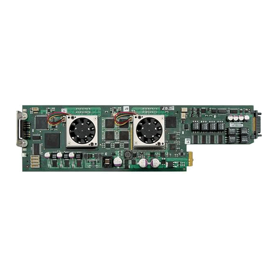
Page 18: Module Layout
= BNC connectors for unbalanced AES3id PVD 5600 D = SubD connector for balanced AES3 Module Rear Termination Panels Cooling Fans Note. Cooling fan operation is monitored and alarmed with the module alarm LED and also within the LYNX control system. Page 18 of 50... -
Page 19: Connections
P VD 5660 Reference Manual. Rev 1.3 Connections Video The PVD 5660 uses standard 75 Ohm BNC connectors. We recommend the use of high quality video cable for digital video connections to reduce the risk of errors due to excessive cable attenuation. Max cable lengths the module will support are shown below. SDTV = 250m Belden 8281 (270Mbits/s) HDTV = 140m Belden 1694A (1.4Gbits/s) Note. -
Page 20: Installation
NOTE. The use of the optional control system is mandatory for the control and setup of this module. If you do not have the control system, then please contact your LYNX representative for details on how to upgrade your rack with the LYNX control system. -
Page 21: Firmware Options
P VD 5660 Reference Manual. Rev 1.3 Firmware Options The basic module is a single channel frame synchronizer and SDTV ARC with full audio support, providing four user mapped outputs. With the addition of the following firmware options the performance and features of the module can be greatly enhanced and tailored to meet a specific application. -
Page 22: Down Conversion Option (Oc-5660-Dwn)
P VD 5660 Reference Manual. Rev 1.3 Down Conversion Option (OC-5660-DWN) With the addition of this option basic down conversion capability (HDTV to SDTV) can be added to the module (2 instances are required to provide two internal channels of down conversion). -
Page 23: Up/Down/Cross Conv. Option (Oc-5660-Upxd)
P VD 5660 Reference Manual. Rev 1.3 Up/Down/Cross Conv. Option (OC-5660-UPXD) The addition of this option provides a single channel of high quality up, down and cross conversion to the module (which can be used in addition to the basic down conversion options if installed). -
Page 24: Cross Conversion
P VD 5660 Reference Manual. Rev 1.3 Cross Conversion When used in cross conversion mode the module will cross convert the video signal between 1080i and 720P formats within the same frame rate. Image size and Positioning This option also provides the ability to manually adjust the image size and position of the converted output. -
Page 25: Settings And Control
P VD 5660 Reference Manual. Rev 1.3 Settings and Control The P VD 5660 module has an integrated micro-controller, which enables the module to be configured and controlled locally using the multifunction switch and 4 character dot matrix display, or from remote using a GUI interface when using one of the optional controllers and control software. -
Page 26: Menu Structure
P VD 5660 Reference Manual. Rev 1.3 Menu Structure The Menu structure is defined in the next table, and can be used to help navigating through the menu system. ENTER moves between levels UP/DOWN moves between items within the level When a new setting is entered the system will jump back one level in the menu system. -
Page 27: Led Status Indicators
P VD 5660 Reference Manual. Rev 1.3 LED Status Indicators The P VD 5660 module has LED indicators that serve as alarm and status indication for the module. Function is described below. SDI 1 Status LED 1 LED Color Indication Green SDI 1 Present and OK Yellow... -
Page 28: Control System Gui
The above screenshot shows the complete module GUI. The Device info area contains information about the module including name and firmware revision. If used as part of a larger system (using the LYNX central control system) the modules position and physical location is displayed above the “locate” button. -
Page 29: Main Tab
P VD 5660 Reference Manual. Rev 1.3 There are a number of “Tabs” along the top of the screen which splits up the module settings into a number of logical displays. The various GUI screens and primary functions are described below. Main Tab This screen is the main interface and is presented first when the module is displayed in the GUI. -
Page 30: Video Proc Tab
P VD 5660 Reference Manual. Rev 1.3 Video Proc Tab This tab will display the configuration screen for the two basic down converters (OC-5660-DWN option) this screen can also be accessed by clicking on the “Conv 1” or “Conv 2” boxed in the flow diagram on the main GUI screen. Note. -
Page 31: Device Status
P VD 5660 Reference Manual. Rev 1.3 It is also possible for the synchronizer to configure the output frame rate based upon the connected reference. This is the default setting for the module. Possible settings are: • 50Hz • 59.94Hz •... -
Page 32: Converter Source
P VD 5660 Reference Manual. Rev 1.3 Options are installed via a license strings (purchased separately) these are entered into the module to activate the options. Option licenses are managed / entered using the Options Tab in the GUI. Converter Source It’s possible to select the signal source into each down converter. -
Page 33: Hq Scaler Source
P VD 5660 Reference Manual. Rev 1.3 The screen below shows the controls provided for the HQ Up, Down, Cross and Aspect Ratio Conversion. HQ Scaler Source This selection allows the input source to the scaler to be selected, this can also be set using the signal routing selections on the Main Tab. -
Page 34: Output Proc Tabs
P VD 5660 Reference Manual. Rev 1.3 Note. It is also possible to manually drag the input and output cropping extremities using the mouse pointer on the GUI. Simply position the mouse over the green line you wish to move, click and drag the line to the desired point on the image. Drag Green Lines with mouse Output Proc Tabs... -
Page 35: Aperture Correction
P VD 5660 Reference Manual. Rev 1.3 Aperture Correction Horizontal aperture correction is provided for each output channel, which can be used to sharpen or soften the video signal. (This is sometimes required for down converted video signals as the filtering process rolls off the high frequency very slightly). If adjusted in the positive direction this will increase sharpness, if adjusted in the negative direction this will soften the image. -
Page 36: Test Pattern Pre-Select
P VD 5660 Reference Manual. Rev 1.3 Note. If the pres selected test pattern is selected this will be used in the respective channel video format and NOT influenced by the “Test Pattern Standard” selection mentioned below. Test Pattern Pre-select A wide range of patterns is provided which can be selected using the drop down selection provided. -
Page 37: Timing Tab
P VD 5660 Reference Manual. Rev 1.3 Timing Tab All manually adjustable delays for audio and video can be set in the GUI shown below. The video delay can be adjusted for the four SDI outputs independently. The audio delay can be set at various positions: SDI in: Delay of the embedded audio after de-embedding SDI out:... -
Page 38: Aes Input Crossbar Tab
P VD 5660 Reference Manual. Rev 1.3 Note: The Synchronizer will auto track the audio delay to the frame synchronizer video delay. The adjustments provided here are offsets relative to the internal tracking delay. The audio delay offset can be set at various positions as graphically shown in the audio processing chain. -
Page 39: Pathway 1
P VD 5660 Reference Manual. Rev 1.3 inputs are the vertical component of the crossbar. The audio pathways out of the crossbar are horizontal. Routing an AES pair is achieved by clicking on the cross point with the mouse cursor. Pathway 1 The first 8 AES signals out of the crossbar (01…08) represent “Pathway 1”... -
Page 40: Aes Proc Tab
P VD 5660 Reference Manual. Rev 1.3 AES Proc Tab This provides access to the internal audio processing functions such as audio gain / mute / phase invert / overload and silence detection per audio mono channel (overload and silence are indicated by color of the respective symbol: Green = OK Red = overload or silence. -
Page 41: Aes Out Tab
P VD 5660 Reference Manual. Rev 1.3 AES Out Tab This section is used to configure the external AES outputs. 4 outputs are provided and any of the internal audio signals can be routed to the external outputs if required. **Timing Zones See Note below All inputs to the crossbar are shown horizontally and the 4 x External AES outputs are... - Page 42 P VD 5660 Reference Manual. Rev 1.3 Select “Mono Controls” from this small submenu and a new mini cross point control box is displayed The Mini cross bar looks like shown, and permits full control over the routing of the left and right audio channels within the AES cross point selected.
-
Page 43: Output Mux Tabs
P VD 5660 Reference Manual. Rev 1.3 If the mouse pointer is positioned on the cross point using the “ctrl” key and left mouse button click will toggle the settings. Use of this function takes a little practice - as the position of the pointer on the correct cross point quadrant is critical. -
Page 44: User Presets Tab
P VD 5660 Reference Manual. Rev 1.3 User Presets Tab Note: This Tab is only visible if the OC-5660-USET option is installed. This Tab allows the user to store and recall 3 sets of additional module presets (settings), and also configure GPI switching between any two of the 3 stored presets and / or the current module settings (4 total). -
Page 45: Setting Gpi Control Of Preset Selections
P VD 5660 Reference Manual. Rev 1.3 Setting GPI control of Preset selections In some cases its desirable to switch quickly between two sets of stored presets, this can be achieved using the external GPI trigger 1. Next to each preset there are two radio buttons which allow for the selection of GPI switching 2. -
Page 46: Options Tab
Click the “request code” button next to the channel you wish to activate. A number will be displayed, Please forward this number with your purchase order to your authorized LYNX dealer or representative. When you receive the license string simply type it (or paste it using the windows clipboard) into the area provided and press “activate”. -
Page 47: Events Tab
(This has no impact or influence over the internally error log maintained by the LYNX control system) (Internal LYNX error logging and external SNMP traps can be configured independently). Note. The simulated event is part of the GUI simulator and allows us to force a particular error condition for testing and demonstration purposes. -
Page 48: Specifications
P VD 5660 Reference Manual. Rev 1.3 Specifications Video Inputs Signal Type Serial digital video SMPTE 292M, 344M, 259M-C Input standards HDTV: 1080i 59.94Hz / 60Hz / 50Hz / 720P 59.94Hz / 60Hz / 50Hz SDTV: 525 59.94Hz / 625 50Hz. (Upgradeable if additional format support is released) No. - Page 49 Local alphanumeric display with integrated menu system for setting “basic” module parameters. Remote Control Comprehensive remote control and status monitoring supported when used with a LYNX Controller option. The use of the control system is mandated for this module External GPI Single GPI input on BNC connector.
-
Page 50: Service
Technical support is also available from our website. Please do not return products to LYNX without an RMA. Please contact your authorized dealer or reseller for more details. More detailed product information and product updates may be available on our web site: www.lynx-technik.com...
Need help?
Do you have a question about the P VD 5660 D and is the answer not in the manual?
Questions and answers