
Related Manuals for Telit Wireless Solutions E866 Series


Summary of Contents for Telit Wireless Solutions E866 Series
- Page 1 XE866 INTERFACES USER GUIDE 1VV0301260 Rev.2 2016-09-01 Arrow.com. Downloaded from...
- Page 2 APPLICABILITY TABLE GE866-QUAD INTERFACE 3990251275 UE866-N3G INTERFACE 3990251273 LE866-SV1 INTERFACE 3990251313 LE866A1-KK INTERFACE 3990251343 XE866 INTERFACES USER GUIDE 1VV0301260 Rev.2 – 2016-09-01 2 of 79 Reproduction forbidden without Telit Communications PLC written authorization – All Rights Reserved Arrow.com. Arrow.com. Downloaded from Downloaded from...
- Page 3 DISCLAIMER LEGAL NOTICE These Specifications are general guidelines pertaining to product selection and application and may not be appropriate for your particular project. Telit (which hereinafter shall include, its agents, licensors and affiliated companies) makes no representation as to the particular products identified in this document and makes no endorsement of any product.
- Page 4 HIGH RISK MATERIALS Components, units, or third-party products contained or used with the products described herein are NOT fault-tolerant and are NOT designed, manufactured, or intended for use as on-line control equipment in the following hazardous environments requiring fail-safe controls: the operation of Nuclear Facilities, Aircraft Navigation or Aircraft Communication Systems, Air Traffic Control, Life Support, or Weapons Systems (“High Risk Activities").
-
Page 5: Table Of Contents
CONTENTS INTRODUCTION Scope Audience Contact Information, Support List of acronyms Text Conventions 1.6. Related Documents OVERVIEW GE866-QUAD Interface Description Physical dimensions Interface Details Connectors Position Jumpers Setting SO101 & SO104 - EVK2 Connection Antenna Connectors 3.3.4.1 SO103 - MAIN Antenna connector PL105 - Power Supply Setting SIM Holder and SIM Detection RESET... - Page 6 FIRMWARE UPDATE Interface Schematics Components Layout UE866-N3G Interface Description Physical dimensions Interface Details Connectors Position Jumpers Setting SO101 & SO104 - EVK2 Connection Antenna Connectors 4.3.4.1 SO103 - GSM Antenna connector PL105 - Power Supply Setting SIM Holder and SIM Detection RESET STAT LED Expansion Connectors...
- Page 7 5.3.4.2 SO106 - Diversity Antenna connector PL105 - Power Supply Setting SIM Holder and SIM Detection RESET STAT LED Expansion Connectors 5.3.10.1 PL101 5.3.10.2 PL202 Stand-alone setup FIRMWARE UPDATE Interface Schematics Components Layout SAFETY RECOMMENDATIONS Disposal of this product in the European Union Disposal of this product in other countries outside the European Union DOCUMENT HISTORY Revisions...
-
Page 8: Introduction
INTRODUCTION Scope The Aim of this document is the handling description of the EVK2 Interfaces for the products based on xE866 Form Factor. Audience All given information shall be used as a guide and a starting point for properly developing of your product. Obviously this document cannot cover all the hardware solutions and products that may be designed. -
Page 9: List Of Acronyms
List of acronyms Acronym Description ARFCN Absolute Radio Frequency Channel Number Attention command Clear To Send Data Carrier Detect Data Communication Equipment Digital Cellular System Data Set Ready Data Terminal Equipment DTMF Dual Tone Multi Frequency Data Terminal Ready GLONASS Global positioning system maintained by the Russian Space Forces GNSS Any single or combined satellite navigation system (GPS, GLONASS... -
Page 10: Text Conventions
Text Conventions Danger – This information MUST be followed or catastrophic equipment failure or bodily injury may occur. Caution or Warning – Alerts the user to important points about integrating the module, if these points are not followed, the module and end user equipment may fail or malfunction. -
Page 11: Overview
OVERVIEW The Telit Evaluation Kit (EVK2) provides a robust, future-proof and flexible environment to streamline all application development based on Telit GSM/GPRS, UMTS/HSPA, CDMA 1x/EV-DO, and LTE module families, significantly reducing time-to-market. The EVK2 kit includes a motherboard where to connect the Interface board of a Telit module. This concept allows the EVK2 to be used across various form factors and product generations, both present and future. -
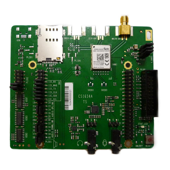
Page 12: Ge866-Quad Interface
GE866-QUAD INTERFACE Description This board allows easily interfacing the GE866-QUAD modules with the EVK2 and testing their functionalities. Physical dimensions Item Value Length 92,00 mm Width 107,00 mm Height 25,00 mm XE866 INTERFACES USER GUIDE 1VV0301260 Rev.2 – 2016-09-01 12 of 79 Reproduction forbidden without Telit Communications PLC written authorization –... -
Page 13: Interface Details
Interface Details Connectors Position XE866 INTERFACES USER GUIDE 1VV0301260 Rev.2 – 2016-09-01 13 of 79 Reproduction forbidden without Telit Communications PLC written authorization – All Rights Reserved Arrow.com. Arrow.com. Arrow.com. Arrow.com. Arrow.com. Arrow.com. Arrow.com. Arrow.com. Arrow.com. Arrow.com. Arrow.com. Arrow.com. Arrow.com. Downloaded from Downloaded from Downloaded from... -
Page 14: Jumpers Setting
Jumpers Setting The following picture shows the jumpers placement and their default settings. Details in the following paragraphs. XE866 INTERFACES USER GUIDE 1VV0301260 Rev.2 – 2016-09-01 14 of 79 Reproduction forbidden without Telit Communications PLC written authorization – All Rights Reserved Arrow.com. -
Page 15: So101 & So104 - Evk2 Connection
SO101 & SO104 - EVK2 Connection The connections between the Interface and the EVK2 is done through two 2x40 pin female connectors present on the bottom (SO101 and SO104). Theirs pin functions are listed in the following tables: SO101 Signal Type Function Do not connect... - Page 16 SO101 Signal Type Function DC voltage Power DC voltage Power DC voltage Power DC voltage Power EAR_HF+ AC Out Voltage Audio EAR_MT- AC Out Voltage Audio EAR_HF- AC Out Voltage Audio EAR_MT+ AC Out Voltage Audio Do not connect MIC_HF- AC In Voltage Audio MIC_MT+...
- Page 17 SO104 Signal Type Function VBATT DC voltage Power VBATT DC voltage Power VBATT DC voltage Power VBATT DC voltage Power DC voltage Power DC voltage Power DC voltage Power DC voltage Power Do not connect Do not connect DC voltage Power DC voltage Power...
- Page 18 SO104 Signal Type Function Do not connect Do not connect SIMIO Digital Signal SIM Data I/O SIMCLK Digital Signal SIM Clock SIMRST Digital Signal SIM Reset SIMVCC DC voltage SIM Power SIMIN Digital Signal SIM Presence detector Do not connect Do not connect Do not connect DC voltage...
-
Page 19: Antenna Connectors
Antenna Connectors 3.3.4.1 SO103 - MAIN Antenna connector The GE866 is provided by one single RF antenna. The connector is SO103 and it is a female SMA. A WCDMA compatible antenna (Refer to the product’s HW user guide) must be connected to SO103. PL105 - Power Supply Setting The PL105 connector is permitting to configure how to supply the module. -
Page 20: Sim Holder And Sim Detection
SIM Holder and SIM Detection The Interface is provided by a SIM Holder (SO102). The SIM holder lines are in parallel to the lines connected to the SIM Holder on EVK2 so it is not allowed to have a SIM in both holders. Due to the fact the product is not provided by a dedicated pin for the HW SIM Presence detection, it is possible to select one GPIO to be used for this function. -
Page 21: Expansion Connectors
Expansion Connectors 3.3.9.1 PL101 The connector carries the following signals: PL101 Signal Function Ground VBATT_AUX Interface Power supply GPIO_01/DVI_RX Digital audio interface RX ADC_IN 11 bit ADC converter, 0-1.2V DC VRTC Real Time Clock backup DAC_OUT DAC converter Power supply for external devices/Power ON VAUX/PWRMON Monitor GPIO_06... - Page 22 PL101 Signal Function GPIO_03/DVI_TX Digital audio interface TX GPIO_04/DVI_CLK Digital audio interface Clock GPIO_01/DVI_WA0 Digital audio interface WA0 GPIO_07/STAT_LED Status pin GPIO_06 GPIO GPIO_05 GPIO XE866 INTERFACES USER GUIDE 1VV0301260 Rev.2 – 2016-09-01 22 of 79 Reproduction forbidden without Telit Communications PLC written authorization – All Rights Reserved Arrow.com.
-
Page 23: Pl202
3.3.9.2 PL202 The connector carries the following signals: PL202 Signal Function TX_AUX AUX UART TX (Output from Module) TX_AUX (Lev. Adapter) AUX UART TX (Input of Level Adapter) RX_AUX AUX UART RX (Input to Module) RX_AUX (Lev. Adapter) AUX UART RX (Output from Level Adapter) There are two Jumpers on this connector that permit to connect the AUX UART of the module to the level adapter (1.8V to 2.8V DC and vice versa) interfacing the EVK2. -
Page 24: Audio Section And Settings
Audio Section and Settings The Interface is equipped with an Audio Codec usable in connection with the module’s DVI. In case there is a need to use the Module’s Analog Audio lines it is possible to access them on the Interface connectors. -
Page 25: Audio Outputs
3.3.10.3 Audio Outputs The Interface is provided by a set of possible Audio Outputs to interface the Audio circuitry (i.e. Audio Codec) or directly the module. Its configuration could be set using the Jumpers on PL301. You could refer to the “PL301 - Audio Settings” paragraph for the details. 3.3.10.3.1 EAR Output This part of the circuit permits to amplify the audio signal coming from the Codec or directly from the... -
Page 26: Pl301 - Audio Settings
PL301 – Audio Settings 3.3.10.4 The Audio Configuration could be done using the Jumpers on PL301. 3.3.10.4.1 DVI and I2C Connections This connector allows configuring GPIOs from 1 to 6 as DIGITAL AUDIO INTERFACE. This configuration is done setting the jumpers as indicated below: DVI and I2C connections Jumpers Signal on Module... -
Page 27: Speaker Connections
Audio Downlink Setting on PL301 Jumpers Signal Description on Pin 29-31 SPK+ (Modem) From Module 30-32 33-35 SPK- (Modem) From Module 34-36 31-33 LOUTP From CODEC 32-34 ROUTP 35-37 LOUTN From CODEC 36-38 ROUTN The Default setting is DVI connected Uplink from SO301 to CODEC, Downlink from CODEC. 3.3.10.5 Speaker connections It is also possible to connect an external speaker by using the two Test Points, as shown in the figure... -
Page 28: Audio Accessories
Audio Accessories The following tables show the suggested specification to obtain the best performance from off-the-shelf accessories. 3.3.11.1.1 Headset Specification The typical characteristics of the Microphone and Earpiece to be used with the Interface are: Microphone Item Value Nominal sensitivity -45dBV /1Pa (+/- 3dB) Line coupling... -
Page 29: Stand-Alone Setup
Stand-alone setup The GE866 Interface could be used in Stand alone (without the EVK2 mainboard) with the following remarks: The Power supply could be provided connecting a Power supply to SO104 or PL105 (removing the Jumpers) The Power supply level has to be carefully verified in the Module’s HW User Guide ... -
Page 30: Interface Schematics
Interface Schematics XE866 INTERFACES USER GUIDE 1VV0301260 Rev.2 – 2016-09-01 30 of 79 Reproduction forbidden without Telit Communications PLC written authorization – All Rights Reserved Arrow.com. Arrow.com. Arrow.com. Arrow.com. Arrow.com. Arrow.com. Arrow.com. Arrow.com. Arrow.com. Arrow.com. Arrow.com. Arrow.com. Arrow.com. Arrow.com. Arrow.com. Arrow.com. - Page 31 XE866 INTERFACES USER GUIDE 1VV0301260 Rev.2 – 2016-09-01 31 of 79 Reproduction forbidden without Telit Communications PLC written authorization – All Rights Reserved Arrow.com. Arrow.com. Arrow.com. Arrow.com. Arrow.com. Arrow.com. Arrow.com. Arrow.com. Arrow.com. Arrow.com. Arrow.com. Arrow.com. Arrow.com. Arrow.com. Arrow.com. Arrow.com. Arrow.com. Arrow.com.
- Page 32 XE866 INTERFACES USER GUIDE 1VV0301260 Rev.2 – 2016-09-01 32 of 79 Reproduction forbidden without Telit Communications PLC written authorization – All Rights Reserved Arrow.com. Arrow.com. Arrow.com. Arrow.com. Arrow.com. Arrow.com. Arrow.com. Arrow.com. Arrow.com. Arrow.com. Arrow.com. Arrow.com. Arrow.com. Arrow.com. Arrow.com. Arrow.com. Arrow.com. Arrow.com.
- Page 33 XE866 INTERFACES USER GUIDE 1VV0301260 Rev.2 – 2016-09-01 33 of 79 Reproduction forbidden without Telit Communications PLC written authorization – All Rights Reserved Arrow.com. Arrow.com. Arrow.com. Arrow.com. Arrow.com. Arrow.com. Arrow.com. Arrow.com. Arrow.com. Arrow.com. Arrow.com. Arrow.com. Arrow.com. Arrow.com. Arrow.com. Arrow.com. Arrow.com. Arrow.com.
-
Page 34: Components Layout
Components Layout XE866 INTERFACES USER GUIDE 1VV0301260 Rev.2 – 2016-09-01 34 of 79 Reproduction forbidden without Telit Communications PLC written authorization – All Rights Reserved Arrow.com. Arrow.com. Arrow.com. Arrow.com. Arrow.com. Arrow.com. Arrow.com. Arrow.com. Arrow.com. Arrow.com. Arrow.com. Arrow.com. Arrow.com. Arrow.com. Arrow.com. Arrow.com. -
Page 35: Ue866-N3G Interface
UE866-N3G INTERFACE Description This board allows easily interfacing the UE866-N3G modules with the EVK2 and testing their functionalities. Physical dimensions Item Value Length 92,00 mm Width 107,00 mm Height 25,00 mm XE866 INTERFACES USER GUIDE 1VV0301260 Rev.2 – 2016-09-01 35 of 79 Reproduction forbidden without Telit Communications PLC written authorization –... -
Page 36: Interface Details
Interface Details Connectors Position XE866 INTERFACES USER GUIDE 1VV0301260 Rev.2 – 2016-09-01 36 of 79 Reproduction forbidden without Telit Communications PLC written authorization – All Rights Reserved Arrow.com. Arrow.com. Arrow.com. Arrow.com. Arrow.com. Arrow.com. Arrow.com. Arrow.com. Arrow.com. Arrow.com. Arrow.com. Arrow.com. Arrow.com. Arrow.com. -
Page 37: Jumpers Setting
Jumpers Setting The following picture shows the jumpers placement and their default settings. Details in the following paragraphs. XE866 INTERFACES USER GUIDE 1VV0301260 Rev.2 – 2016-09-01 37 of 79 Reproduction forbidden without Telit Communications PLC written authorization – All Rights Reserved Arrow.com. -
Page 38: So101 & So104 - Evk2 Connection
SO101 & SO104 - EVK2 Connection The connections between the Interface and the EVK2 is done through two 2x40 pin female connectors present on the bottom (SO101 and SO104). Theirs pin functions are listed in the following tables: SO101 Signal Type Function Do not connect... - Page 39 SO101 Signal Type Function DC voltage Power DC voltage Power DC voltage Power DC voltage Power Do not connect Do not connect Do not connect Do not connect Do not connect Do not connect Do not connect Do not connect Do not connect DC voltage Power...
- Page 40 SO104 Signal Type Function VBATT DC voltage Power VBATT DC voltage Power VBATT DC voltage Power VBATT DC voltage Power DC voltage Power DC voltage Power DC voltage Power DC voltage Power Do not connect Do not connect DC voltage Power DC voltage Power...
- Page 41 SO104 Signal Type Function Do not connect Do not connect SIMIO Digital Signal SIM Data I/O SIMCLK Digital Signal SIM Clock SIMRST Digital Signal SIM Reset SIMVCC DC voltage SIM Power SIMIN Digital Signal SIM Presence detector Do not connect Do not connect Do not connect DC voltage...
-
Page 42: Antenna Connectors
Antenna Connectors 4.3.4.1 SO103 - GSM Antenna connector The UE866 is provided by one single RF antenna. The connector is SO103 and it is a female SMA. A WCDMA compatible antenna (Refer to the product’s HW user guide) must be connected to SO103. PL105 - Power Supply Setting The PL105 connector is permitting to configure how to supply the module. -
Page 43: Sim Holder And Sim Detection
SIM Holder and SIM Detection The Interface is provided by a SIM Holder (SO102). The SIM holder lines are in parallel to the lines connected to the SIM Holder on EVK2 so it is not allowed to have a SIM in both holders. Due to the fact the product is not provided by a dedicated pin for the HW SIM Presence detection, it is possible to select one GPIO to be used for this function. -
Page 44: Expansion Connectors
Expansion Connectors 4.3.10.1 PL101 The connector carries the following signals: PL101 Signal Function Ground VBATT_AUX Interface Power supply GPIO_01/DVI_RX Digital audio interface RX ADC_IN 11 bit ADC converter, 0-1.2V DC VRTC Real Time Clock backup DAC_OUT DAC converter Power supply for external devices/Power ON VAUX/PWRMON Monitor GPIO_06... - Page 45 PL101 Signal Function GPIO_03/DVI_TX Digital audio interface TX GPIO_04/DVI_CLK Digital audio interface Clock GPIO_01/DVI_WA0 Digital audio interface WA0 GPIO_07/STAT_LED Status pin GPIO_06 GPIO GPIO_05 GPIO XE866 INTERFACES USER GUIDE 1VV0301260 Rev.2 – 2016-09-01 45 of 79 Reproduction forbidden without Telit Communications PLC written authorization – All Rights Reserved Arrow.com.
-
Page 46: Pl202
4.3.10.2 PL202 The connector carries the following signals: PL202 Signal Function TX_AUX AUX UART TX (Output from Module) TX_AUX (Lev. Adapter) AUX UART TX (Input of Level Adapter) RX_AUX AUX UART RX (Input to Module) RX_AUX (Lev. Adapter) AUX UART RX (Output from Level Adapter) There are two Jumpers on this connector that permit to connect the AUX UART of the module to the level adapter (1.8V to 2.8V DC and vice versa) interfacing the EVK2. -
Page 47: Audio Inputs
4.3.11.2 Audio Inputs The Interface Board is provided by a set of possible Audio inputs to interface the Audio circuitry (i.e. Audio Codec) or directly the module. Its configuration could be set using the Jumpers on PL301. You could refer to the “PL301 - Audio Settings” paragraph for the details. 4.3.11.2.1 Microphone Input This circuit permits to connect a standard electret microphone. -
Page 48: Audio Outputs
Or using the PL306 connector where the pin-out is the following: 1 BIAS/R_MIC Signal 2 GND 3 L_MIC Signal 4.3.11.3 Audio Outputs The Interface is provided by a set of possible Audio Outputs to interface the Audio circuitry (i.e. Audio Codec). -
Page 49: Pl301 - Audio Settings
PL301 – Audio Settings 4.3.11.4 The Audio Configuration could be done using the Jumpers on PL301. 4.3.11.4.1 DVI and I2C Connections This connector allows configuring GPIOs from 1 to 6 as DIGITAL AUDIO INTERFACE. This configuration is done setting the jumpers as indicated below: DVI and I2C connections Jumpers Signal on Module... - Page 50 Audio Downlink Setting on PL301 Jumpers Signal Description on Pin 29-31 From Module SPK+ (Modem) 30-32 (NOT SUPPORTED) 33-35 From Module SPK- (Modem) 34-36 (NOT SUPPORTED) 31-33 LOUTP From CODEC 32-34 ROUTP 35-37 LOUTN From CODEC 36-38 ROUTN The Default setting is DVI connected Uplink from SO301 to CODEC, Downlink from CODEC. XE866 INTERFACES USER GUIDE 1VV0301260 Rev.2 –...
-
Page 51: Audio Accessories
Audio Accessories The following tables show the suggested specification to obtain the best performance from off-the-shelf accessories. 4.3.12.1.1 Headset Specification The typical characteristics of the Microphone and Earpiece to be used with the Interface are: Microphone Item Value Nominal sensitivity -45dBV /1Pa (+/- 3dB) Line coupling... -
Page 52: Stand-Alone Setup
Stand-alone setup The UE866 Interface could be used in Stand alone (without the EVK2 mainboard) with the following remarks: The Power supply could be provided connecting a Power supply to SO104 or PL105 (removing the Jumpers) The Power supply level has to be carefully verified in the Module’s HW User Guide ... -
Page 53: Interface Schematics
Interface Schematics XE866 INTERFACES USER GUIDE 1VV0301260 Rev.2 – 2016-09-01 53 of 79 Reproduction forbidden without Telit Communications PLC written authorization – All Rights Reserved Arrow.com. Arrow.com. Arrow.com. Arrow.com. Arrow.com. Arrow.com. Arrow.com. Arrow.com. Arrow.com. Arrow.com. Arrow.com. Arrow.com. Arrow.com. Arrow.com. Arrow.com. Arrow.com. - Page 54 XE866 INTERFACES USER GUIDE 1VV0301260 Rev.2 – 2016-09-01 54 of 79 Reproduction forbidden without Telit Communications PLC written authorization – All Rights Reserved Arrow.com. Arrow.com. Arrow.com. Arrow.com. Arrow.com. Arrow.com. Arrow.com. Arrow.com. Arrow.com. Arrow.com. Arrow.com. Arrow.com. Arrow.com. Arrow.com. Arrow.com. Arrow.com. Arrow.com. Arrow.com.
- Page 55 XE866 INTERFACES USER GUIDE 1VV0301260 Rev.2 – 2016-09-01 55 of 79 Reproduction forbidden without Telit Communications PLC written authorization – All Rights Reserved Arrow.com. Arrow.com. Arrow.com. Arrow.com. Arrow.com. Arrow.com. Arrow.com. Arrow.com. Arrow.com. Arrow.com. Arrow.com. Arrow.com. Arrow.com. Arrow.com. Arrow.com. Arrow.com. Arrow.com. Arrow.com.
- Page 56 XE866 INTERFACES USER GUIDE 1VV0301260 Rev.2 – 2016-09-01 56 of 79 Reproduction forbidden without Telit Communications PLC written authorization – All Rights Reserved Arrow.com. Arrow.com. Arrow.com. Arrow.com. Arrow.com. Arrow.com. Arrow.com. Arrow.com. Arrow.com. Arrow.com. Arrow.com. Arrow.com. Arrow.com. Arrow.com. Arrow.com. Arrow.com. Arrow.com. Arrow.com.
-
Page 57: Components Layout
Components Layout XE866 INTERFACES USER GUIDE 1VV0301260 Rev.2 – 2016-09-01 57 of 79 Reproduction forbidden without Telit Communications PLC written authorization – All Rights Reserved Arrow.com. Arrow.com. Arrow.com. Arrow.com. Arrow.com. Arrow.com. Arrow.com. Arrow.com. Arrow.com. Arrow.com. Arrow.com. Arrow.com. Arrow.com. Arrow.com. Arrow.com. Arrow.com. -
Page 58: Le866 Interface
LE866 INTERFACE Description This board allows easily interfacing the LE866 modules with the EVK2 and testing their functionalities. Physical dimensions Item Value Length 92,00 mm Width 107,00 mm Height 25,00 mm XE866 INTERFACES USER GUIDE 1VV0301260 Rev.2 – 2016-09-01 58 of 79 Reproduction forbidden without Telit Communications PLC written authorization –... -
Page 59: Interface Details
Interface Details Connectors Position XE866 INTERFACES USER GUIDE 1VV0301260 Rev.2 – 2016-09-01 59 of 79 Reproduction forbidden without Telit Communications PLC written authorization – All Rights Reserved Arrow.com. Arrow.com. Arrow.com. Arrow.com. Arrow.com. Arrow.com. Arrow.com. Arrow.com. Arrow.com. Arrow.com. Arrow.com. Arrow.com. Arrow.com. Arrow.com. -
Page 60: Jumpers Setting
Jumpers Setting The following picture shows the jumpers placement and their default settings. Details in the following paragraphs. XE866 INTERFACES USER GUIDE 1VV0301260 Rev.2 – 2016-09-01 60 of 79 Reproduction forbidden without Telit Communications PLC written authorization – All Rights Reserved Arrow.com. -
Page 61: So101 & So104 - Evk2 Connection
SO101 & SO104 - EVK2 Connection The connections between the Interface and the EVK2 is done through two 2x40 pin female connectors present on the bottom (SO101 and SO104). Theirs pin functions are listed in the following tables: SO101 Signal Type Function Do not connect... - Page 62 SO101 Signal Type Function DC voltage Power DC voltage Power DC voltage Power DC voltage Power Do not connect Do not connect Do not connect Do not connect Do not connect Do not connect Do not connect Do not connect Do not connect DC voltage Power...
- Page 63 SO104 Signal Type Function VBATT DC voltage Power VBATT DC voltage Power VBATT DC voltage Power VBATT DC voltage Power DC voltage Power DC voltage Power DC voltage Power DC voltage Power Do not connect Do not connect DC voltage Power DC voltage Power...
- Page 64 SO104 Signal Type Function Do not connect Do not connect SIMIO Digital Signal SIM Data I/O SIMCLK Digital Signal SIM Clock SIMRST Digital Signal SIM Reset SIMVCC DC voltage SIM Power SIMIN Digital Signal SIM Presence detector Do not connect Do not connect Do not connect DC voltage...
-
Page 65: Antenna Connectors
Antenna Connectors 5.3.4.1 SO103 - Main Antenna connector The connector SO103 (Female SMA) is related to the MAIN ANTENNA of the LE866. An LTE compatible antenna (Refer to the product’s HW user guide) must be connected to SO103. 5.3.4.2 SO106 - Diversity Antenna connector The connector SO106 (Female SMA) is related to the Diversity Antenna input of the LE866. -
Page 66: Sim Holder And Sim Detection
SIM Holder and SIM Detection The Interface is provided by a SIM Holder (SO102). The SIM holder lines are in parallel to the lines connected to the SIM Holder on EVK2 so it is not allowed to have a SIM in both holders. Due to the fact the product is not provided by a dedicated pin for the HW SIM Presence detection, it is possible to select one GPIO to be used for this function. -
Page 67: Expansion Connectors
Expansion Connectors 5.3.10.1 PL101 The connector carries the following signals: PL101 Signal Function Ground VBATT_AUX Interface Power supply GPIO_01/DVI_RX Digital audio interface RX ADC_IN 11 bit ADC converter, 0-1.2V DC VRTC Real Time Clock backup DAC_OUT DAC converter Power supply for external devices/Power ON VAUX/PWRMON Monitor GPIO_06... - Page 68 PL101 Signal Function GPIO_03/DVI_TX Digital audio interface TX GPIO_04/DVI_CLK Digital audio interface Clock GPIO_01/DVI_WA0 Digital audio interface WA0 GPIO_07/STAT_LED Status pin GPIO_06 GPIO GPIO_05 GPIO XE866 INTERFACES USER GUIDE 1VV0301260 Rev.2 – 2016-09-01 68 of 79 Reproduction forbidden without Telit Communications PLC written authorization – All Rights Reserved Arrow.com.
-
Page 69: Pl202
5.3.10.2 PL202 The connector carries the following signals: PL202 Signal Function TX_AUX AUX UART TX (Output from Module) TX_AUX (Lev. Adapter) AUX UART TX (Input of Level Adapter) RX_AUX AUX UART RX (Input to Module) RX_AUX (Lev. Adapter) AUX UART RX (Output from Level Adapter) There are two Jumpers on this connector that permit to connect the AUX UART of the module to the level adapter (1.8V to 2.8V DC and vice versa) interfacing the EVK2. -
Page 70: Stand-Alone Setup
Stand-alone setup The Interface could be used in Stand alone (without the EVK2 mainboard) with the following remarks: The Power supply could be provided connecting a Power supply to SO104 or PL105 (removing the Jumpers) The Power supply level has to be carefully verified in the Module’s HW User Guide ... -
Page 71: Interface Schematics
Interface Schematics XE866 INTERFACES USER GUIDE 1VV0301260 Rev.2 – 2016-09-01 71 of 79 Reproduction forbidden without Telit Communications PLC written authorization – All Rights Reserved Arrow.com. Arrow.com. Arrow.com. Arrow.com. Arrow.com. Arrow.com. Arrow.com. Arrow.com. Arrow.com. Arrow.com. Arrow.com. Arrow.com. Arrow.com. Arrow.com. Arrow.com. Arrow.com. - Page 72 XE866 INTERFACES USER GUIDE 1VV0301260 Rev.2 – 2016-09-01 72 of 79 Reproduction forbidden without Telit Communications PLC written authorization – All Rights Reserved Arrow.com. Arrow.com. Arrow.com. Arrow.com. Arrow.com. Arrow.com. Arrow.com. Arrow.com. Arrow.com. Arrow.com. Arrow.com. Arrow.com. Arrow.com. Arrow.com. Arrow.com. Arrow.com. Arrow.com. Arrow.com.
- Page 73 XE866 INTERFACES USER GUIDE 1VV0301260 Rev.2 – 2016-09-01 73 of 79 Reproduction forbidden without Telit Communications PLC written authorization – All Rights Reserved Arrow.com. Arrow.com. Arrow.com. Arrow.com. Arrow.com. Arrow.com. Arrow.com. Arrow.com. Arrow.com. Arrow.com. Arrow.com. Arrow.com. Arrow.com. Arrow.com. Arrow.com. Arrow.com. Arrow.com. Arrow.com.
- Page 74 XE866 INTERFACES USER GUIDE 1VV0301260 Rev.2 – 2016-09-01 74 of 79 Reproduction forbidden without Telit Communications PLC written authorization – All Rights Reserved Arrow.com. Arrow.com. Arrow.com. Arrow.com. Arrow.com. Arrow.com. Arrow.com. Arrow.com. Arrow.com. Arrow.com. Arrow.com. Arrow.com. Arrow.com. Arrow.com. Arrow.com. Arrow.com. Arrow.com. Arrow.com.
-
Page 75: Components Layout
Components Layout XE866 INTERFACES USER GUIDE 1VV0301260 Rev.2 – 2016-09-01 75 of 79 Reproduction forbidden without Telit Communications PLC written authorization – All Rights Reserved Arrow.com. Arrow.com. Arrow.com. Arrow.com. Arrow.com. Arrow.com. Arrow.com. Arrow.com. Arrow.com. Arrow.com. Arrow.com. Arrow.com. Arrow.com. Arrow.com. Arrow.com. Arrow.com. -
Page 76: Safety Recommendations
SAFETY RECOMMENDATIONS READ CAREFULLY Be sure the use of this product is allowed in the country and in the environment required. The use of this product may be dangerous and has to be avoided in the following areas: Where it can interfere with other electronic devices in environments such as hospitals, airports, aircrafts, etc Where there is risk of explosion such as gasoline stations, oil refineries, etc It is responsibility of the user to enforce the country regulation and the specific environment regulation. -
Page 77: Disposal Of This Product In The European Union
Disposal of this product in the European Union According to the WEEE Directive 2012/19/EU, the crossed-out wheeled bin symbol on the product or on its packaging indicates that the product must not be disposed of with your other household waste. For equipment in private household, it’s user’s responsibility to dispose of his waste equipment by handing it over to a designated collection point for the recycling of waste electrical and electronic equipment. -
Page 78: Document History
DOCUMENT HISTORY Revisions Revision Date Changes Rev 0 2016/02/10 First issue Rev 1 2016/04/13 Updated Jumpers Layout Rev 2 2016/09/01 Added LE866A1-KK XE866 INTERFACES USER GUIDE 1VV0301260 Rev.2 – 2016-09-01 78 of 79 Reproduction forbidden without Telit Communications PLC written authorization – All Rights Reserved Arrow.com. - Page 79 Arrow.com. Arrow.com. Arrow.com. Arrow.com. Arrow.com. Arrow.com. Arrow.com. Arrow.com. Arrow.com. Arrow.com. Arrow.com. Arrow.com. Arrow.com. Arrow.com. Arrow.com. Arrow.com. Arrow.com. Arrow.com. Arrow.com. Arrow.com. Arrow.com. Arrow.com. Arrow.com. Arrow.com. Arrow.com. Arrow.com. Arrow.com. Arrow.com. Arrow.com. Arrow.com. Arrow.com. Arrow.com. Arrow.com. Arrow.com. Arrow.com. Arrow.com. Arrow.com. Arrow.com. Arrow.com. Arrow.com. Arrow.com.
Need help?
Do you have a question about the E866 Series and is the answer not in the manual?
Questions and answers