
Related Manuals for GW Instek GSP-8180TG


Summary of Contents for GW Instek GSP-8180TG
- Page 1 Spectrum Analyzer GSP-8000 Series USER MANUAL GW INSTEK PART NO. ISO-9001 CERTIFIED MANUFACTURER...
- Page 2 October 2023 This manual contains proprietary information, which is protected by copyright. All rights are reserved. No part of this manual may be photocopied, reproduced or translated to another language without prior written consent of the Good Will company. The information in this manual was correct at the time of printing. However, Good Will continues to improve products and reserves the right to change specification, equipment, and maintenance procedures at any time without notice.
-
Page 3: Table Of Contents
Table of Contents Table of Contents SAFETY INSTRUCTIONS ..........5 USER NOTICE ..............10 General Inspection ........... 10 Safety Precaution before Operation ......11 Electro-static Discharge (ESD) Protection ....13 First Time to Power on ..........14 GETTING STARTED ............15 Package Contents and Accessories ...... - Page 4 GSP-8000 series User Manual Peak Search .............. 61 Marker ..............65 Marker→ ..............69 Marker Function ............71 Measurement ............73 Measure Setup ............77 System ..............78 File ................81 Quick Save ..............82 Save ................82 FAQ ................84 APPENDIX ..............
-
Page 5: Safety Instructions
SAFETY INSTRUCTIONS AFETY INSTRUCTIONS This chapter contains important safety instructions that you must follow when operating the GSP-8000, and when keeping it in storage. Read the following before operating the GSP- 8000 to ensure your safety and to keep the GSP- 8000 in the best possible condition. - Page 6 GSP-8000 series User Manual Do not dispose electronic equipment as unsorted municipal waste. Please use a separate collection facility or contact the supplier from which this instrument was purchased. Safety Guidelines Do not place any heavy object on the GSP-8000. General Guideline •...
- Page 7 SAFETY INSTRUCTIONS AC Input voltage range: 100-240Vac; Power Supply • Frequency: 50/60Hz WARNING Connect the protective grounding conductor of • the AC power cord to an earth ground, to avoid electrical shock. Disconnect the power cord before cleaning. Cleaning the •...
- Page 8 GSP-8000 series User Manual Location: Indoor Storage • environment Relative Humidity: < 80% • Temperature: −20°C to 70°C • Do not dispose this instrument as unsorted Disposal municipal waste. Please use a separate collection facility or contact the supplier from which this instrument was purchased.
- Page 9 SAFETY INSTRUCTIONS Power cord for the United Kingdom When using the GSP-8000 in the United Kingdom, make sure the power cord meets the following safety instructions. NOTE: This lead/appliance must only be wired by competent persons WARNING: THIS APPLIANCE MUST BE EARTHED IMPORTANT: The wires in this lead are coloured in accordance with the following code: Green/ Yellow:...
-
Page 10: User Notice
Check the Complete Instrument If there is any physical damage, operational fault, or performance issue please contact your distributor or GW Instek’s local office. If there is any damage to the instrument please ensure you keep the original packaging. Ideally you should always keep the original packaging if the instrument must be returned for repair. -
Page 11: Safety Precaution Before Operation
USER NOTICE Safety Precaution before Operation Check Power Supply The analyzer is equipped with a three-wire power cord in accordance with international safety standards. The product must be grounded properly before being powered on, as floating or improper ground may cause damage to the instrument or personal injury. - Page 12 GSP-8000 series User Manual Improper grounding may cause damage to the WARNING instrument, or result in personal injury. Make sure the grounding conductor of the spectrum analyzer is grounded before turning on the instrument. Always use a well-grounded power source. Do not use an external power cable, power cord or an auto transformer without grounded protection.
-
Page 13: Electro-Static Discharge (Esd) Protection
USER NOTICE Electro-static Discharge (ESD) Protection ESD is an issue often ignored by users. Damage from ESD on the instrument is unlikely to occur immediately but will significantly reduce the reliability of it. Therefore, ESD precautions should be implemented in the work environment, and applied daily. Generally, there are two steps to manage ESD protection: 1. -
Page 14: First Time To Power On
GSP-8000 series User Manual First Time to Power on Connect the three-pin AC power cord into the instrument. Insert the plug into a power socket provided with a protective ground. Check the power source before turning on the WARNING spectrum analyzer, to protect the device from damage. 1. -
Page 15: Getting Started
GETTING STARTED ETTING STARTED This chapter introduces the front / rear panel, the user interface and explains how to use the instrument with a measurement example demonstration. Package Contents and Accessories ......16 Front Panel Overview ..........17 Rear Panel ..............19 Front Panel Function Key .......... -
Page 16: Package Contents And Accessories
GSP-8000 series User Manual Package Contents and Accessories The GSP-8000 has a number of standard and optional accessories that can be ordered. For more information please visit the GW Instek website at www.gwinstek.com or consult your authorized distributor for details. Standard Description Accessories... -
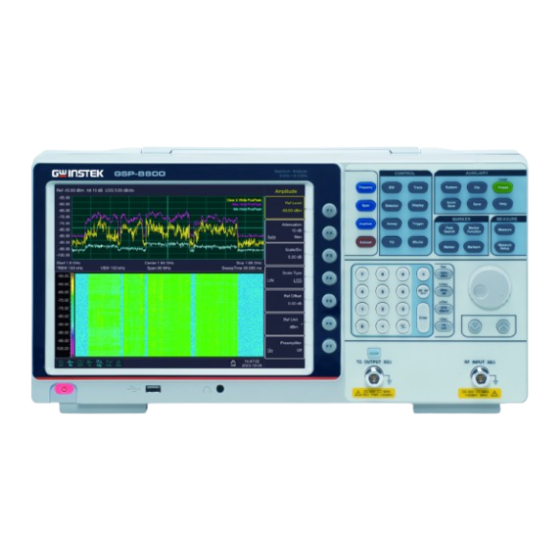
Page 17: Front Panel Overview
GETTING STARTED Front Panel Overview 1024x768 color LCD display. The display 1. LCD shows the soft keys for the current function, frequency, amplitude and marker information. The F1 to F7 function keys directly 2. Menu soft correspond to the soft keys on the right- keys hand side of display. - Page 18 GSP-8000 series User Manual tree in the File function 6. RF Input The RF input may be connected to a device via a N type connector. connector When input attenuator is higher than 10 dB, the RF port Note input signal must be less than +30 dBm. Input voltage at RF input port must not be higher than 50 V DC to avoid damage to the attenuator and input mixer tracking generator.
-
Page 19: Rear Panel
GETTING STARTED Rear Panel 1. Handle Stow the handle for mobile use. 2 AC power AC: frequency 50Hz/60Hz ±10%, single- connector phase alternative 220V±15% or 110V±15% 3. Stool To adjust the angle of the device 4. LAN Through this interface, the analyzer can be interface connected to your local network for remote control. - Page 20 GSP-8000 series User Manual 8. Lock hole You can lock the spectrum analyzer to a fixed location using the security lock (please buy it yourself) to secure the spectrum analyzer.
-
Page 21: Front Panel Function Key
GETTING STARTED Front Panel Function Key Basic keys Utility keys Control keys Mode Marker function measure Basic keys Activates the center-frequency function, and accesses the frequency function menu. Activates the frequency sweep span function, and set Full Span\Zero Span\Last Span. Activates the reference level function, and accesses the amplitude softkeys, with which you set functions that affect data on the vertical axis. - Page 22 GSP-8000 series User Manual Accesses the softkeys that allow you to configure detector functions. Accesses the softkeys that allow you to control what is displayed on the analyzer, including the display line, graticule, Label, Menu Hide, Brightness and Screen Sleep. Accesses the softkeys that allow you to set the sweep time, select the sweep mode of the analyzer.
- Page 23 GETTING STARTED Sets the parameters for the selected measurement function. Utility keys Accesses the softkeys that allow you to get the system information, or set the system parameters. Accesses the softkeys that allow you to configure the file system of the analyzer. Resets the analyzer to the factory settings or user state.
-
Page 24: Parameter Input
GSP-8000 series User Manual Parameter Input Specific parameter values are able to be entered using the numeric keypad, knob, and directional keys. Numeric Keypad Numbers 0-9 are available to be used. Numeric keys A decimal point “.” will be inserted at the Decimal cursor position when this key is pressed. - Page 25 GETTING STARTED When pressed, the system will complete the Enter key input process and insert a default measurement unit for the parameter automatically. Unit keys include GHz/dBm/Sec, Unit keys MHz/dB/mSec, kHz/dBmV/μSec and Hz/mV/nSec. After entering the desired numbers, choose an appropriate unit to complete the input.
-
Page 26: User Interface
GSP-8000 series User Manual User Interface Marker function No. Name Description Related Key Reference level Reference level → [Ref Level] Display input → [Attenuation] Attenuation attenuation setting Can choose → [Scale Type] Amplitude logarithmic or Division Type linear Display Division →... - Page 27 GETTING STARTED Trace Type and Trace Mode Detector Type Function of current Menu title menu belongs to. Menu item of Menu item current function 10. Stop Frequency Display Stop →[Stop Frequency] Frequency 11. Date/time Display system →[Date/Time] date and time 12.
-
Page 28: Build-In Help
GSP-8000 series User Manual Build-in Help The built-in help provides information that refers to every function key and menu key on the front panel. Users can view this help information if required. Basic Measurement Basic measurements include, input signal frequency and amplitude display, marked by a frequency marker. - Page 29 GETTING STARTED To clearly observe the signal, reduce the frequency span to 1 MHz and set the center frequency to 100MHz. 2. Setting Center Frequency Press the Frequency button and select Center frequency on corresponding pop up menu. Input "100" and select the unit as MHz on the numeric keypad.
- Page 30 GSP-8000 series User Manual 5. Press the Detector button and set the detection type to positive peak. The signal at a higher resolution Please note that resolution bandwidth, video bandwidth and frequency span are self- adapted. They adjust to certain values according to frequency span.
- Page 31 GETTING STARTED on Y axis. Here we reduce to 20dB reference level to increase the dynamic range. 2. Press the Amplitude button. The amplitude setting menu will pop up and the reference level soft key will be activated. The reference level can be input at the top left of the display grid.
- Page 32 GSP-8000 series User Manual ENU INTEPRETATION This chapter provides you with the information on using the front panel of the spectrum analyzer. Frequency ..............37 Center Freq ................37 Start Freq ................38 Stop Freq ................38 Freq Step Auto Manual ............39 Freq Offset ................
-
Page 33: Menu Intepretation
MENU INTEPRETATION Detector ..............52 Detector type comparison ...........52 Pos Peak ................52 Neg Peak ................52 Sample ..................52 Normal .................53 Voltage Avg................53 RMS Avg ................53 Quasi-Peak ................53 Display ..............54 Full Screen ................54 Display Line ................54 Ampt Graticule ..............54 Label ..................54 Menu Hide On Off ...............54 Brightness ................54 Screen Sleep On Off .............54... - Page 34 GSP-8000 series User Manual Modulation► ............... 60 AM► ..................60 FM► ..................60 Peak Search .............. 61 Peak Search ............61 Mkr > CF ................61 Peak-Peak ................61 Next Peak ................62 Left Peak ................63 Right Peak ................63 Cont Peak On Off ..............
- Page 35 MENU INTEPRETATION Time Spec On Off ..............73 ACPR On Off ................73 Chanel Power On off ............73 OBW On Off .................74 Pass-Fail► ................74 Window Meas► ..............74 Window Meas On Off ............74 Limit Line On Off ..............74 Freq Line On Off ..............74 Limit Set Up Low ..............74 Freq Set Start Stop ...............75 Window Sweep On Off ............75...
- Page 36 GSP-8000 series User Manual Last Page ................81 Operations► ............... 81 Quick Save ..............82 Save ................82 Screen Pixmap► ..............82 Trace Data► ................ 82 User State ................82 Limit Line ................82 QuickSaveSet► ..............83...
-
Page 37: Frequency
MENU INTEPRETATION Frequency The frequency range of a channel can be expressed by either of two groups of parameters: Start Frequency and Stop Frequency; or Center Frequency and Span. If any such parameter is changed, the others would be adjusted automatically in order to ensure the coupling relationship among them = ( f ) / 2... -
Page 38: Start Freq
GSP-8000 series User Manual Start Freq Sets the start frequency of the sweep. When pressed, the frequency mode is switched to Start Freq and Stop Freq in order to enter the desired parameter data. The span and center frequency are changed Key Points •... -
Page 39: Freq Step Auto Manual
MENU INTEPRETATION Freq Step Auto Manual Sets the step of center/start/stop frequency. Changing the frequency range in a fixed step continuously switches the channel to be measured. The frequency step type could be “Manual” or Key Points • “Auto”. In Auto mode, the CF step is 1/10 of span if it is in Non-zero span mode or equals 25% of RBW while in Zero span mode;... -
Page 40: Freq Ref Internal External
GSP-8000 series User Manual While this function activated (frequency offset isn’t 0), you can modify this parameter using the numeric keys, knob or direction keys. Freq Ref Internal External Set the reference frequency as internal or external input, this is regarded as whole device reference. -
Page 41: Span
MENU INTEPRETATION Span Set the spectrum analyzer to span mode. When press the SPAN button, Span, Full Span, Zero Span and Last Span will be available to configure. You can modify span using the numeric keys, knob or direction keys. Use numeric key or Zero Span to clear span. Span Sets the frequency range of the sweep. -
Page 42: Zero Span
GSP-8000 series User Manual Zero Span Sets the span of the analyzer to 0 Hz. Both the start and stop frequencies will equal the center frequency and the horizontal axis will denote time. The analyzer here is measuring the time domain characteristics of amplitude, located at the corresponding frequency point. -
Page 43: Amplitude
MENU INTEPRETATION Amplitude Sets the amplitude parameters of the analyzer. Through these parameters, signals under measurement can be displayed at an optimal view with minimum error. The pop out amplitude menu includes Ref Level, Attenuation, Scale/Div, Scale Type, Ref Offset, Ref Unit and Preamplifier. -
Page 44: Attenuation
GSP-8000 series User Manual Attenuation Sets the front attenuator of the RF input in order to permit big signals (or small signals) to pass from the mixer with low distortion (or low noise). It only works under internal mixer mode to adjust input attenuator insider analyzer. -
Page 45: Scale Type
MENU INTEPRETATION By changing the scale, the displayed amplitude Key Points • range is adjusted. The amplitude that can be displayed is from • reference level minus 10 times the current scale value to the reference level. You can modify this parameter using the •... -
Page 46: Ref Unit
GSP-8000 series User Manual The changing of this value changes both the Key Points • readout of the reference level and the amplitude readout of the marker, but will not impact the position of the curve on the screen. You can modify this parameter using the •... -
Page 47: Autoset
MENU INTEPRETATION Autoset Searches for signals automatically throughout the full frequency range, adjusts the frequency and amplitude to their optimum and realizes one-key signal search and auto setting of parameters. Some parameters such as reference level, scale, • and input attenuation may be changed during the auto tune. -
Page 48: Bandwidth
GSP-8000 series User Manual Bandwidth Sets the RBW (Resolution Bandwidth) and VBW (Video Bandwidth) parameters of the analyzer. Pop out the setting menu includes RBW, VBW, and EMI Filter►. Adjust the resolution bandwidth ranging from 1Hz-1MHz. Use numeric key, step key or knob to switch resolution bandwidth. The underline under Auto or Manual means Auto mode or Manual mode. - Page 49 MENU INTEPRETATION EMI Filter (Only apply to - Opt. 02 EMI Settings) ► Pop out the menu for EMI measurement bandwidth. EMI bandwidth Turn on or off EMI measurement resolution On Off bandwidth. 1MHz Set EMI measurement resolution to 1MHz. 120kHz Set EMI measurement resolution to 120kHz.
-
Page 50: Trace
GSP-8000 series User Manual Trace As the sweep signal is displayed as a trace on the screen, you can set parameters about the trace using this key. The analyzer allows for up to five traces to be displayed at one time, and press this key to check the menu for trace. -
Page 51: Operations
MENU INTEPRETATION Operations► Enter trace math related sub menu. 1 ↔ 2 Exchange the trace stock 1 data with trace stock 2 and place them in display mode. 2-DL → 2 Deduct display line value in trace stock 2. This function execute once when activated. -
Page 52: Detector
GSP-8000 series User Manual Detector While displaying a wider span, each pixel contains spectrum information associated with a larger subrange. That is, several samples may fall on one pixel. Which of the samples will be represented by the pixel depends on the selected detector type. Press this key to pop out the relevant menu includes Pos Peak, Neg Peak, Sample, Normal, Voltage Avg, RMS Avg (EMI Option) and Quasi-Peak (EMI Option). -
Page 53: Normal
MENU INTEPRETATION Normal When noise is detected, the positive and negative peaks are alternately displayed, otherwise only positive peaks are displayed. Voltage Avg Average all the data of the sampling data segment and display the result as the value of the pixel. RMS Avg Calculates the average power of all the samples in the sample bucket. -
Page 54: Display
GSP-8000 series User Manual Display Controls the screen display of the analyzer, such as setting the on or off for, display line, amplitude scale, grid, label, Menu Hide, Brightness and Screen Sleep. Full Screen Set to full-screen display graphical interface, press any key to exit. Display Line When this menu is on, an adjustable horizontal reference line is activated on the screen. -
Page 55: Sweep
MENU INTEPRETATION Sweep Sets parameters about the Sweep time and mode including Sweep Time, Sweep Single and Sweep Cont. Sweep Time Sets the time interval for the analyzer to complete a sweep. In non-zero span, the analyzer uses the shortest sweep time on the basis of the current RBW and VBW settings if Auto is selected. -
Page 56: Trigger
GSP-8000 series User Manual Trigger Sets the trigger type and other associated parameters, menu includes Free and Video. Free Set the trigger mode to the free trigger mode so that the scan trigger is as fast as possible with the spectrum analyzer. It meets the trigger conditions at any time, that is, continue to generate a trigger signal. -
Page 57: Tracking Generator
MENU INTEPRETATION Tracking Generator When the Tracking Generator is On, a signal with the same frequency of the current sweep signal will be output from the TG OUTPUT 50Ω terminal on the front panel. Press the key will pop out related menu includes TG►, Track Gen On Off, Output Power Level, Reference, Position, Do normalize and Normalize On Off. -
Page 58: Normalize On Off
GSP-8000 series User Manual Normalize On Off Turn on or off the Normalize function. -
Page 59: Mode
MENU INTEPRETATION Mode Mode There has three modes for display: Spectrum, Demod and Modulation. Default is Spectrum mode. In Demod mode, it set the volume of the speaker on audio demodulation. Enter the modulation settings, the spectrum analyzer supports AM, FM digital demodulation. -
Page 60: Modulation
GSP-8000 series User Manual Modulation► Enter the demodulation mode soft menu. Including AM, FM. AM► Enter AM demodulation soft menu. Carrier Freq Set the carrier frequency of the AM modulation signal. IF BW Set the demodulation bandwidth to auto or manual mode. -
Page 61: Peak Search
MENU INTEPRETATION Peak Search Executes peak searching immediately and opens the Peak setting menu. If Max is selected from the Peak Search option, Key Points • it will search and mark the maximum on the trace. If Min is selected from the Peak Search option, •... -
Page 62: Next Peak
GSP-8000 series User Manual Next Peak Searches the peak whose amplitude is the closest to that of the current peak. The peak is then identified with a marker. When this key is pressed repeatedly, you can quickly find a lower peak. -
Page 63: Left Peak
MENU INTEPRETATION Left Peak Searches the nearest peak located to the left side of the current peak and meets the current peak and peak thresholds condition. The peak is then identified with a marker. Right Peak Searches the nearest peak located to the right side of the current peak and meets the current peak and peak thresholds condition. -
Page 64: Peak List On Off
GSP-8000 series User Manual Peak List On Off Turn the peak list on or off. Display 10 peaks that meet the set conditions. -
Page 65: Marker
MENU INTEPRETATION Marker The marker appears as a rhombic sign (shown below) for identifying the point on the trace. We can easily readout the parameters of the marked point on the trace, such as the amplitude, frequency and sweep time. The analyzer allows for up to three groups of Key Points •... -
Page 66: Trace 1 2 3 4 5
GSP-8000 series User Manual Trace 1 2 3 4 5 In the trace measurement, the frequency scale used to activate the traces. Normal One of the marker types, which is used to measure the values of X (Frequency or Time) or Y (Amplitude) at certain point of the trace. When selected, a marker will appear with its own digital ID such as “1”... -
Page 67: Off
MENU INTEPRETATION activated, press Delta to place the still frequency scale to the active marker. The displayed amplitude difference is expressed in dB, or is the linear unit in terms of the corresponding scale. The Reference Marker will be activated at the Key Points •... -
Page 68: All Off
GSP-8000 series User Manual All Off Turns off all the opened markers and the related functions. The marker won’t show again. Marker Table Turns on or off the display of all marker table. -
Page 69: Marker
MENU INTEPRETATION Marker→ A soft menu associated with the marker function is popped out for setting the other system parameters (such as Center frequency, Reference level) by current marker readings. These menus relate to the frequency of the spectrum analyzer, whether the sweep width and marker are in normal or delta marker mode. -
Page 70: Mkr->Stop
GSP-8000 series User Manual If Delta Marker is selected, the start frequency will be set to the frequency at which the Delta Marker is located. The function is invalid in Zero span mode. Mkr->Stop Sets the stop frequency of the analyzer based on the frequency of the current marker. -
Page 71: Marker Function
MENU INTEPRETATION Marker Function Executes specific marker soft menu. Function Off Turn off marker measurement function. NdB On Off Enables the N dB BW measurement or sets the value of N. The N dB BW denotes the frequency difference between points that are located on both sides of the current marker while the amplitude falls off (N<0) or rises (N>0) N dB separately, When the measurement starts, the analyzer will... - Page 72 GSP-8000 series User Manual count also pops up an additional counter function for the soft menu, including Freq Count On Off Freq Count On Turn on or off the frequency counter mode. This function is invalid when the trace signal generator is activated.
-
Page 73: Measurement
MENU INTEPRETATION Measurement Provide a variety of advanced measurement functions, pop-up spectrum analyzer built-in and user-defined measurement function soft menu, turn on or off the time spectrum, adjacent channel power measurement, channel power measurement, occupied bandwidth, Pass-Fail measurement menu. Measure off You can directly close the currently running measurement function, you can also choose to close the measurement menu. -
Page 74: Obw On Off
GSP-8000 series User Manual OBW On Off Turn on or off the occupied bandwidth measurement. Press the Measure Setup button to pop up the parameter setting soft menu for occupying the bandwidth measurement. Occupied Bandwidth is a measure of the bandwidth occupied by the transmitter signal can be measured from the total power ratio within the in-band power span, with a default value of 99% (the user can set this value). -
Page 75: Freq Set Start Stop
MENU INTEPRETATION Freq Set Start Stop Start and stop frequencies for scanning line for editing. Window Sweep On Off Turn window sweep on or off. When the window sweep is on, only the window formed by the intersection of the amplitude line and the frequency line is scanned. -
Page 76: Edit
GSP-8000 series User Manual Amplitude The region has been edited on the whole superimposed on a degree, so that it can move up or down, easy to measure. Does not affect the amplitude setting of the spectrum analyzer. Edit► UpLine Edit ► Upper line editing is used to edit the control line above the trace, depending on the trace. -
Page 77: Measure Setup
MENU INTEPRETATION Measure Setup Measurement setting menu for the corresponding measurement parameter settings when adjacent channel power, channel power, occupied bandwidth measurement mode is turned on. Channel BW Set the bandwidth of the channel power measurement, and set the total display power percentage of bandwidth. Channel Interval Set the center frequency difference of the primary channel to the adjacent channel. -
Page 78: System
GSP-8000 series User Manual System A soft menu for system parameter settings pops up. Including System Info ►, Firmware Update, Option►, LAN►, Shutdown On Off, Language►, Date/Time►. For first time you use the spectrum analyzer, set the date and time, the system will store the settings, restart the machine after power off won’t change the settings. -
Page 79: Lan
MENU INTEPRETATION LAN► Pop out the relative menu for network configuring. Used to set the IP address of the LAN port. Mask Set the subnet mask parameter. Gate Set default gateway address. DHCP On Off To reset the LAN. Toggles the LAN configuration between DHCP and manual settings. -
Page 80: Power On/Preset
GSP-8000 series User Manual Power On/Preset► Used to set the analyzer power on parameters or reset parameters. Power Set► Power on parameter settings include Factory and User Preset► Power on parameter settings include Factory and User To save the current system configuration as a user- Note defined configuration, press the [Save] panel key and select the [User Status] menu item. -
Page 81: File
MENU INTEPRETATION File Pop up file management soft menu. Storage Int Ext In the directory state, view the latest stored files. Type► To check file type under directory, includes screen image, trace data, limit line and display all. First Page Display first page of current directory. -
Page 82: Quick Save
GSP-8000 series User Manual Quick Save Save the contents of the current screen quickly. Save It’s available to save screenshot, trace data, or user status. Screen Pixmap► Enter screenshot save soft menu, you can choose to save screenshots to local or flash memory, the image file format is bmp, the lower left corner of the screen status display bar will display the saved screenshots information. - Page 83 MENU INTEPRETATION QuickSaveSet► Set quick save the screen, trace file, system configuration or limit line data.
-
Page 84: Faq
RF input connector. If there is still no signal display, there may be a problem with the spectrum analyzer hardware circuit. Please contact GW Instek for service. Q3. The signal amplitude readout is not precise. - Page 85 → [frequency reference Internal External].If the frequency is still not precise, then the spectrum analyzer LO has lost its phase lock, please contact GW Instek for service. For more information, contact your local dealer or GW Instek at www.gwinstek.com / marketing@goodwill.com.tw.
-
Page 86: Appendix
GSP-8000 series User Manual PPENDIX Specifications This chapter lists the technical specifications and general technical specifications of the spectrum analyzer. Unless otherwise stated, the technical specifications apply to the following conditions: The instrument has been preheated for 60 • minutes before use. The instrument is in the calibration cycle and •... - Page 87 APPENDIX Aging rate <1ppm/year Initial Accuracy < 1ppm SSB PHASE NOISE fc=1 GHz, RBW= 1 kHz, VBW=1kHz, 20°C ~ 30°C, avearge ≥ 40 10 kHz < -104 dBc/Hz Offset from Carrier 100 kHz < -106 dBc/Hz (Typical) 1 MHz < -115 dBc/Hz (Typical) BANDWIDTH 1Hz to 1MHz (1-3-5-10 steps by sequence) Resolution Bandwidth...
- Page 88 GSP-8000 series User Manual 1 GHz ~ 1.8 GHz, <-160dBm (typical), <-150 dBm 100 kHz ~ 1MHz, <-135 dBm (typical), <-128dBm GSP-8380 1 MHz ~ 1 GHz, <-160dBm (typical), <-150 dBm 1 GHz ~ 3.8 GHz, <-160dBm (typical), <-150 dBm 100 kHz ~ 1MHz, <-135dBm (typical), <-128 dBm 1 MHz ~ 500MHz, <-160dBm (typical), <-150 dBm GSP-8800...
- Page 89 APPENDIX Connect 50 Ω load at input port, 0 dB input attenuation, 20°C to 30°C, average ≥ 40, RBW = 300Hz, VBW = 3kHz,SPAN = 2M Residual response <-85 dBm, 1 MHz ~ Max. Frequency Range Input related spurious <-60 dBc, -30 dBm signal at input mixer, 20°C ~ 30°C SWEEP SWEEP TIME 10 ms ~ 3000 s, None-zero Span...
- Page 90 GSP-8000 series User Manual USB Device B Plug, supports USB TMC Remote Control LAN TCP/IP RJ-45, supports 10Base-T/100Base-Tx Interface Mass Memory Internal Memory 256M Bytes Operating 0 °C to 40°C Temperature Temperature Storage -20°C to 70°C Temperature ≤ 95% 0°C to 30°C Relative humidity ≤...
-
Page 91: Gsp-8000 Factory Default Settings
APPENDIX GSP-8000 Factory Default Settings The following default settings are the factory configuration settings for GSP-8000. Factory Settings Parameter Value Frequency 4000.000000 MHz (GSP-8800) Center Frequency 1900.000000 MHz (GSP-8380) 900.000000 MHz (GSP-8180) Start Frequency 0 Hz 8000.000000 MHz (GSP-8800) Stop Frequency 3800.000000 MHz (GSP-8380) 1800.000000 MHz (GSP-8180) 800.000000 MHz (GSP-8800) - Page 92 GSP-8000 series User Manual Detector Detect Type Pos Peak Sweep Sweep Time Auto Sweep Term Continuous Sweep Tracking Source Trace Trace Trace State Clear & Write Trace 1 Math 1<- ->2 Display Full Display Display Line Amplitude Graticule Label Menu Hide Brightness 100% Screen Sleep...
- Page 93 APPENDIX Subnet Mask 255.255.255.0 Gateway 192.168.0.1 Local Language English Date/Time...
-
Page 94: Certificate Of Compliance
GSP-8000 series User Manual Certificate Of Compliance GOOD WILL INSTRUMENT CO., LTD. declare that the CE marking mentioned product satisfies all the technical relations application to the product within the scope of council: Directive: EMC; LVD; WEEE; RoHS The product is in conformity with the following standards or other normative documents: ◎...
Need help?
Do you have a question about the GSP-8180TG and is the answer not in the manual?
Questions and answers