Table of Contents
Advertisement
Operator and
Parts manual
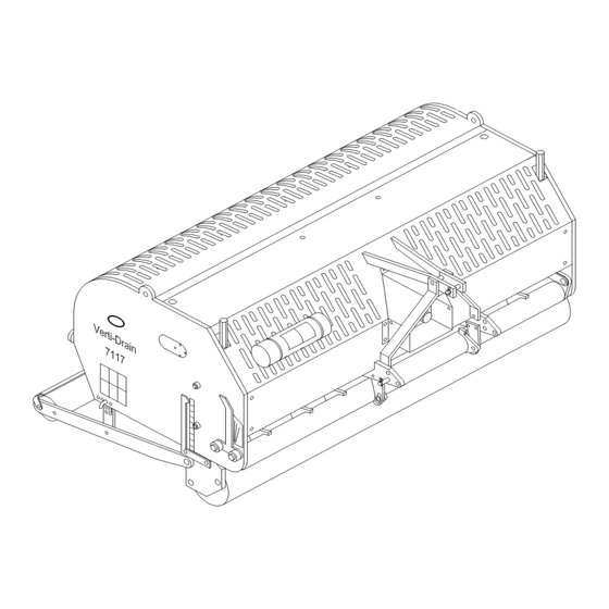
Verti-Drain®
Model 7117
Serial number:
Translation of the original operating instructions
NOTE:
IN ORDER TO ENSURE THE SAFE USE AND TO ACHIEVE THE
BEST PERFORMANCE, IT IS ESSENTIAL THAT THIS
OPERATORS MANUAL IS CAREFULLY READ BEFORE THE
VERTI-DRAIN IS USED.
1703 English 911.120.411
Kwekerijweg 8
3709JA Zeist
The Netherlands
T: (31)306933227
F: (31)306933228
E:
verti-drain@redexim.com
www.redexim.com
Advertisement
Table of Contents

Related Manuals for Redexim 7117


Summary of Contents for Redexim 7117
-
Page 1: Serial Number
Operator and Parts manual Verti-Drain® Kwekerijweg 8 3709JA Zeist The Netherlands T: (31)306933227 Model 7117 F: (31)306933228 verti-drain@redexim.com Serial number: www.redexim.com Translation of the original operating instructions NOTE: IN ORDER TO ENSURE THE SAFE USE AND TO ACHIEVE THE BEST PERFORMANCE, IT IS ESSENTIAL THAT THIS OPERATORS MANUAL IS CAREFULLY READ BEFORE THE VERTI-DRAIN IS USED. -
Page 2: Foreword
FOREWORD. Congratulations on the purchase of your VERTI-DRAIN. To ensure the safe and lasting operations of this VERTI-DRAIN you (and anyone using the machine) should read and understand this user’s manual. A complete knowledge of the contents of the manual is necessary in order to ensure the safe use of this machine. -
Page 3: Safety Instruction
SAFETY INSTRUCTIONS Always use the VERTI-DRAIN with the correct tractor as described in the technical information The user is responsible for a safe Tractor/VERTI-DRAIN combination. The combination must be tested for noise, safety, risk and easy usage. The VERTI-DRAIN is suited exclusively to grass fields. Every VERTI-DRAIN user must be fully informed of the information contained in the user manual. -
Page 4: Table Of Contents
CONTENTS. Paragraphe Description Page Foreword Guarantee conditions Registration card Safety instruction Technical specification First setup, lifting machine from pallet General controls PTO length Use of PTO Slip clutch information and maintenance Working depth adjustment Tine angle adjustment Groundspeed Starting procedures General usage of Verti-Drain 10.0 Transport of Verti-Drain... -
Page 5: Technical Specification
TECHNICAL SPECIFICATIONS. Model 7117 Working width 1.70 mtr (68”) Working depth Up to 150 mm (6”) Tractor speed @ 500 rev’s at PTO Hole spacing 55 mm (2-1/8”) Up to 2.0 km/h (1.25 mph) Hole spacing 90 mm( 3 ½”) Up to 3.2 km/h (2.0 mph) -
Page 6: First Setup, Lifting Machine From Pallet
2.0 FIRST SETUP, LIFTING MACHINE FROM PALLET The machine stands vertically up on the pallet. To remove the pallet and get the machine horizontal on the ground, handle as follows (see fig.1 ): 1. Open the rear cover 2. Connect a cable to lift point * ensure the cable/crane/lift truck can lift minimum 1000 Kg.(2200 lbs). -
Page 7: General Controls
16. When machine is taken of the pallet, remove the upper plug of the gearbox and replace it with the supplied breather. 3.0 GENERAL CONTROLS In fig.2. -
Page 8: Pto
4.0 PTO. The PTO is a very important item. It drives the machine from the tractor and ensures the safe operations when correctly maintained and installed. The PTO shaft has its own CE certification. Read the PTO shaft manual, which is connected to the shaft itself ... -
Page 9: Use Of Pto
4.2 USE OF PTO For the correct use of the PTO, the following items need to be checked: 1. During work the angle of the joints may never exceed 30 degrees 2. The joints have to be in line all the time 3. -
Page 10: Working Depth Adjustment
5.0 WORKING DEPTH ADJUSTMENT. The working depth can be adjusted when the machine is lifted from the ground as follows, see fig. 4: Unscrew nuts 1 at each side of the machine one turn. Screw spindle 3 in or out. Every revolution is 4 mm (0.160"). -
Page 11: Groundspeed
@ From 90 to 75 degrees means more "kick action". This is advised for solid tines, depending on ground conditions, tine size and customer requirements. @ The angle of 90 degrees means that the tines penetrate perpendicular into the ground. This is only true if the machine is correctly set, see fig.1. -
Page 12: Starting Procedures
8.0 STARTING PROCEDURES The starting procedure is VERY important. If the start up is not done as described hereunder, serious damage to the machine may occur. Proceed as follows, see fig.7.: 1. Drive to the spot you want to start the operation. 2. -
Page 13: General Usage Of Verti-Drain
@ Never drive backwards with the tines in or close to the ground. @ NEVER drive backwards, when the lowest tines are less than 120 mm (5") above the ground. If the tines get caught, serious damage will appear on the machine. @ Do not use a hydraulic top link. -
Page 14: Problem Analysis
12.0 PROBLEM ANALYSIS Machine vibrates Crankshaft rotates irregular Machine not at 90 degrees PTO joint angles different PTO joints not in line Tough circumstances Adjust working depth Use thinner/ shorter tines If dry, irrigate first Solid/ hollow tines Wrong tine Change tine, use shorter one Are bending/ breaking Use solids first before hollow to... -
Page 15: Maintenance
After every 500 operating hours. gearbox. 14.0 EU-Declaration We, Redexim Utrechtseweg 127 3702 AC Zeist Holland, hereby declare fully on our authority that the product: VERTI-DRAIN 7117, WITH MACHINE NUMBER AS INDICATED ON THE MACHINE AND IN THIS MANUAL, to which this declaration relates is according to the stipulation of the 2006/42/EC directive for machines as well as the following standards: NEN-EN-ISO 12100 : 2010 and NEN-EN- ISO 13857 : 2008. -
Page 16: Technical Information
15.0 TECHNICAL INFORMATION. Generally speaking, this Verti-Drain is not a complicated machine. A couple of technical items will be explained. If you still have questions, please contact your dealer, who is willing to assist you Fig. 8 In the above fig.8. the torque setting for the several bolts/nuts is given and the timing of the crankshaft. -
Page 17: Torque Settings
15.2 THE CRANKSHAFT In fig.9. the assembly of the crankshaft is given. Also look at the spare part page for a more clear view and setup. On a Verti-Drain 7117 the angle between the handles on the gearbox should be 33,75 degrees. -
Page 18: Replacing Of A Crank And Crank Bearing
15.2.2. REPLACEMENT OF A CRANK WITH BEARING Replacing a crank is necessary when it is cracked or when the big end nuts start to come loose on a regular bases. Either the crank bearing, the crank bearing fitting or the big end pin holes in the crank are damaged. -
Page 19: Assembly Of The Crown Wheel And Pignon
15.4 ASSEMBLY OF THE CROWN WHEEL AND PIGNON 1. Assemble the pignon wheel H, making sure to have the roller bearings unit positioned on the cir-clip side. (see fig. 10) 2. Mount both bearings B into the bearing Houses C. 3. - Page 20 Fig. 10...
-
Page 21: Options, Tines
The rear roller may not be locked. Use always tines with the same length and size. Replace a bent tine immediately. When this is not done, the machine can be unstable. Don’t use any thicker/ longer tines as what is offered by Redexim. -
Page 22: Hollow Tines
@ It is advisable using the dirt protection plates B1 (see fig. 11), that prevents the cores from entering the machine. This part has number 318.302.150. 16.1 OPTIONS, CORE COLLECTOR. An easy mountable core collector is available for the Verti-Drain 7117. The part number is 9300080. ASSEMBLING INSTUCTIONS (see Fig 12):... - Page 23 Assembling the core collector itself: Assemble supports 17 with eye bolts 9 and nuts 10/11 to the main collector plate 1 Screw the side panels 2/3 with bolts 7 and Bushes 8 to the main collector plate 1 Assemble the rubber strip 12 with bolts 13, washers 14 and nuts 6 to the plate 1 Assemble all the sheet springs 4 , well aligned, to the main plate 1.
-
Page 24: Options, Turf Hold Down Kit
The core collector can collect the core for a certain pass length. The length depends on the amount of cores and the sizes. If the area isn’t clean, check the gap between the rubber seal strip 12 and the blade spring tension 4. -
Page 25: Options, Windrow Kit
16.3 OPTIONS, WINDROW KIT. An optional windrow kit can be purchased, see fig. 14. The kit has the following part- number: 211.731.010. A detailed guide on how to assemble the kit can be found in the part pages of this manual. MOUNTING INSTRUCTIONS (see fig. - Page 26 Parts manual...
- Page 27 Redexim Verti-Drain 7117 Page Code 1620 Page 3 Page 8-9 Page 5 Page 4 Page 6 Page 2 Page 7 Page 10: PTO Page 11: Tines Page 12: Adapters and turf hold down kit Page 13: Optional windrow kit Page 14: Optional core collector...
- Page 28 Redexim Verti-Drain 7117 Page Code 1620 111PR013-PP02...
- Page 29 Redexim Verti-Drain 7117 Page Code 1620 PART NUMBER DESCRIPTION REMARKS ITEM 911.260.404 Angle setting label VD 900.260.420 Decall PTO 300 500 900.260.403 Logo Label 911.260.403 Decall Verti-drain 911.280.402 Safety Decall Verti-Drain 911.280.404 Decall close cover 900.280.402 Safety decall manual 900.260.406 Height Label 150 911.260.414...
- Page 30 Redexim Verti-Drain 7117 Page Code 1621 TOOLSET 111PR013-PP03...
- Page 31 1621 PART NUMBER DESCRIPTION REMARKS ITEM 470.061.710 Lock plate 590.342.700 Clamp 468.060.904 Rear plate 456.180.037 Rear cover 7117 2281783 Bottom PTO Protection 2281782 TOP PTO protection cover 456.875.568 Front cover right 456.875.566 Front cover left 404.100.122 Distance bush 446.080.550 Rubber stop 444.803.100...
- Page 32 Redexim Verti-Drain 7117 Page Code 1621 14 9 13 5 14 6 17 9 14 6 13 5 18 6 10 7 36 49 44 32 48 31 Apply 15ml grease inside drawrod Use shim 864.140.012 to create correct length...
- Page 33 Redexim Verti-Drain 7117 Page Code 1621 REMARKS PART NUMBER DESCRIPTION ITEM 802.060.400 Bolt M6 x 40 - ISO 4014 Quantity for one element 830.100.100 Self Lock Nut M10 - ISO 10511 Quantity for one element 804.100.450 Bolt M10 x 45 - ISO 4017 Quantity for one element 804.120.500...
- Page 34 Redexim Verti-Drain 7117 Page Code 1621 4 6 3 10 9 9 10 10 7 9 10 9 10 10 10 9 3 7 9 10 11 7 12 12 8 4 6 8 3 5 3 11 11 7 12...
- Page 35 Redexim Verti-Drain 7117 Page Code 1621 PART NUMBER DESCRIPTION REMARKS ITEM 2281502 Protection plate 804.100.200 Bolt M10 x 20 - ISO 4017 2604527 Distance bush 406.460.120 Distance bush 2465010 Splined shaft long 2465012 Splined shaft short 2447102 Crank plate nut side...
- Page 36 Redexim Verti-Drain 7117 Page Code 1621 12 12 111pr013-PP06...
- Page 37 Cover for lever 468.032.120 Handle for angle adjustment Support bolt assembly central bar 2282186 7117/7316 2691018 U-Bolt M8, for tube 50 402.130.100 Distance bush Ø12.5/Ø40 L=10 2900100 Frame VD 7117 2479102 Clamp 814.120.550 Bolt M12 x 55 - DIN 912 521.161.050 111pr013-PP06...
- Page 38 Redexim Verti-Drain 7117 Page Code 1621 111pr013-PP07...
- Page 39 Lock pin rear roller 802.160.550 Bolt M16 x 55 - ISO 4014 880.060.100 Grease nipple M6 DIN 71412A 742.250.360 Bearing UCFL 205 2281510 Rear roller scraper support 7117 2281512 Rear roller scraper 7117 2343800 Front roller 7117 404.160.160 Pivot bush 468.062.162 Scraper support right 468.062.160...
- Page 40 Redexim Verti-Drain 7117 Page Code 1621 111pr013-PP08...
- Page 41 Redexim Verti-Drain 7117 Page Code 1621 PART NUMBER DESCRIPTION REMARKS ITEM 804.080.200 Bolt M8 x 20 - ISO 4017 2471220 Top plate gearbox 2401203 Casing gearbox 4561000 Tap 1/2" 2401204 Rear part gearbox 820.210.180 Level / fill glass 4067008 Breather gearbox...
- Page 42 Redexim Verti-Drain 7117 Page Code 1621 111pr013-PP09...
- Page 43 Redexim Verti-Drain 7117 Page Code 1621 PART NUMBER DESCRIPTION REMARKS 872.072.250 Circlip D=72 - DIN 472 870.035.160 Circlip d=35 - DIN 471 872.080.250 Circlip D=80 - DIN 472 2462005 Axle 4165400 M40x1.5 KM8 4221078 Lock Washer MB/AW Ø40 4135000 2460400...
- Page 44 Redexim Verti-Drain 7117 PTO Page Code 1612 111pr013-PP11 (PTO)
- Page 45 Redexim Verti-Drain 7117 PTO Page Code 1612 PART NUMBER DESCRIPTION REMARKS ITEM 152140207 Outer tube 151014006 Outer tube yoke 190000014 Outer roll pin 180014130 Cross and 4x circlip kit 141024430 Complete collar yoke 1422400307430 Complete guard Cut to correct length...
- Page 46 Redexim Verti-drain Code 1620 Page 11 Solid tines 7117 Mountig Ø (mm) Tine Size (mm) Tine Size (inch) Part # Adapter 5 x 125 3/16 x 5 311.105.125 J or multi-tine block mini 30+J 8 x 150 5/16 x 6 311.108.150...
- Page 47 Redexim Verti-drain Code 1620 Page 12 Adapter 7117 Tine Size (mm) Tine Size (inch) Part # 3/16 314.205.043 5/16 314.208.043 Adapter 7117 Tine Size (mm) Tine Size (inch) Part # 2451800 Multi-tine block complete WO tines 7117 Tine Size (mm)
- Page 48 Redexim Verti-drain 7117 Optional Windrow kit Page Code 1612 Remove nut and mount lifting eye (17) 111PR013-PP Windrow kit...
- Page 49 Redexim Verti-drain 7117 Optional Windrow kit Page Code 1612 PART NUMBER DESCRIPTION REMARKS ITEM 468.089.000 Windrow plate 464.106.350 Windrow support 406.170.150 Distance bush 406.130.150 Distance bush 802.120.650 Bolt M12 x 65 - ISO 4014 804.120.450 Bolt M12 x 45 - ISO 4017 804.160.450...
- Page 50 Redexim Verti-Drain 7117 Optional Core Collector Page Code 1621 Remove nut and mount lifting eye (22) 111PR013-PP Core collector 7117...
- Page 51 Redexim Verti-Drain 7117 Optional Core Collector Code 1621 PART NUMBER DESCRIPTION REMARKS ITEM 470.049.202 Frame beam 468.035.420 Right side plate 468.035.422 Left side plate 468.013.100 Blade spring 804.080.160 Bolt M8 x 16 - ISO 4017 830.080.080 Self Lock Nut M8 - ISO 10511 804.080.200...
Need help?
Do you have a question about the 7117 and is the answer not in the manual?
Questions and answers