jbc DDE Instruction Manual
2-tool control unit
Hide thumbs
Also See for DDE:
- Instruction manual (17 pages) ,
- Programmer's manual (32 pages) ,
- Programmer's manual (32 pages)
Table of Contents
Advertisement
Quick Links
Advertisement
Table of Contents

Subscribe to Our Youtube Channel
Related Manuals for jbc DDE


Summary of Contents for jbc DDE
- Page 1 INSTRUCTION MANUAL 2-Tool Control Unit...
-
Page 2: Packing List
Ref. 0024077 (100V) Ref. 0027023 0023717 (120V) 0024080 (230V) Features DDE work simultaneously with up to 2 tools and 1 module + 1 pedal for each tool (peripheral module for each tool needed). Display USB-A connector Tilt the display for easy reading... -
Page 3: Connection Example
Handle 40 mm DRS* Stand for ADS* DR560 Stand for Desoldering T210 & T245 Iron Handles Suction Filter* Ref. 0821830 MSE* Module Cable* Electric Desoldering Ref. 0024228 Module for DDE & DME To another Peripheral Pedal P005 * not included... - Page 4 Compatibility Select the equipment that best suit your soldering or desoldering needs. Modular System Peripherals Control Cartridge Stand Tool MSE / MVE P405 Unit Range T210 C210 T245 C245 T470 T210N C210 T245N C245 AP250 C250 AM120 C120 PA120 AT420 C420 HT420 DS360...
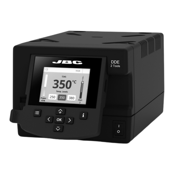
- Page 5 - color gris 200 mm DDE Work Display 130 mm 130 mm DDE offers an intuitive user interface which provides quick access to station parameters. Default PIN: 0105 100 mm Status Bar 19:29 80 mm T245 T245 Tool ºC...
-
Page 6: Advanced Functionalities
Insert a USB flash drive into the USB-A connector to save your soldering process in csv format. Files Station update Download the JBC Update File from www.jbctools.com/software.html Insert the USB flash drive with the file downloaded to the station. Update System Notifications The following icons will be displayed on the screen’s status bar. -
Page 7: Peripheral Setup
ºC para manuales - color gris 200 mm Tool in Actual Temp levels Delay 19:29 Power Port Peripheral Set Up 130 mm 130 mm T245 ºC 1. After connecting the module, enter 19:29 the Peripherals Menu and select the port which you want to join with the module. -
Page 8: Operation
Operation JBC’s Most Efficient Soldering System Our revolutionary technology is able to recover tip temperature extremely quickly. It means the user can work at a lower temperature and improve the soldering quality. The tip temperature is further reduced thanks to the Sleep and Hibernation modes which increase up to 5 times the life of the tip. -
Page 9: Maintenance
If necessary use a tool to lever it off. and replace it in the station. Fuse Fuse Holder Fuse holder - Replace any defective or damaged pieces. Use original JBC spare parts only. - Repairs should only be performed by a JBC authorized technical service. - Page 10 Safety It is imperative to follow safety guidelines to prevent electric shock, injury, fire or explosion. - Do not use the units for any purpose other than soldering or rework. Incorrect use may cause a fire. - The power cord must be plugged into approved bases. Be sure that it is properly grounded before use.
- Page 11 para manuales - color gris 200 mm Notes 130 mm 130 mm 100 mm 80 mm 60 mm 50 mm 40 mm...
- Page 12 Notes...
- Page 13 para manuales - color gris 200 mm Notes 130 mm 130 mm 100 mm 80 mm 60 mm 50 mm 40 mm...
- Page 14 Notes...
-
Page 15: Specifications
Specifications 130 mm 130 mm 2-Tool Control Unit Ref.: DDE-9C 100V 50/60Hz. Input fuse: T5A. Output: 23.5V 100 mm Ref.: DDE-1C 120V 50/60Hz. Input fuse: T4A. Output: 23.5V Ref.: DDE-2C 230V 50/60Hz. Input fuse: T2A. Output: 23.5V - Nominal Power... - Page 16 In order for the warranty to be valid, equipment must be returned, postage paid, to the dealer where it was purchased. Get 1 extra year JBC warranty by registering here: https://www.jbctools.com/productregistration/ within 30 days of purchase. This product should not be thrown in the garbage.
Need help?
Do you have a question about the DDE and is the answer not in the manual?
Questions and answers