Table of Contents
Advertisement
Quick Links
Advertisement
Table of Contents

Related Manuals for jbc DDE-C


Summary of Contents for jbc DDE-C
- Page 1 INSTRUCTION MANUAL Two-Tool Control Unit Ref. DDE-C...
-
Page 2: Packing List
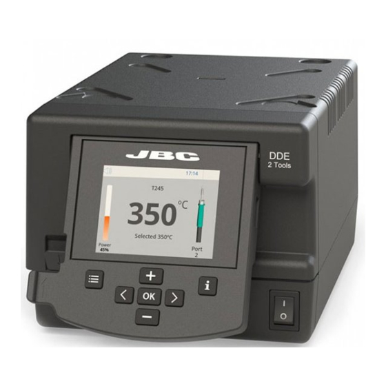
Control Unit ....1 unit Ref. 0010569 (230V) Ref. 0019248 Ref. DDE-1C (120V) 0013671 (100/120V) DDE-2C (230V) DDE-9C (100V) w w w.jbctools.com Two-Tool Control Unit Ref. DDE-C Features USB-A connector 2,8” Color TFT screen Tilt the display for easy reading... - Page 3 Unit Range MVE-A T210-A C210 AD-SD T245-A C245 T470-A C245 T210-NA* C210 T245-NA* DN-SE C245 T470-NA* DDE-C AP-SD AP250-A C250 PA-SD PA120-A C120 HT-SD HT420-A C420 DS-SD DS360-A C360 DR-SD DR560-A C560 * The MNE Nitrogen Flow Regulator is required.
-
Page 4: Operation
Operation The JBC Exclusive Heating System Our revolutionary technology is able to recover tip temperature extremely quickly. It means the user can work at a lower temperature and improve the quality of soldering. The tip temperature is further reduced thanks to the Sleep and Hibernation modes which increase the tip life by 5. -
Page 5: Work Screen
w w w.jbctools.com Work Screen The DDE offers an intuitive user interface which provides quick access to station parameters. Original PIN: 0105 Status bar 17:14 Tool T245 in use ºC Power Temp. Levels indicator Power Port Displayed if temperature levels are activated Station Information... -
Page 6: Process Analysis
Process analysis By pressing Graphics in the main MENU, temperature and power figures in real time are displayed for each port. This helps you decide which tip to use to obtain the best quality solder joints. Graphics 17:14 Power (%) Temperature Power Temp... - Page 7 Soldering Net Remotely manage and monitor as many stations as your PC can handle. 1. Download the JBC Manager software and the user manual from www.jbctools.com/manager.html 2. Connect the stations via USB-B connector and the PC will automatically detect them.
- Page 8 Control Unit RS-232 connection Update the station software 1. Download the JBC Update File from 2. Insert the USB flash drive to the station. www.jbctools.com/software.html and save The icon is diplayed while updating. it on a USB flash drive. Preferably one with no other files.
-
Page 9: Maintenance
If necessary use a tool to lever it off. and replace it in the station. Fuse Fuse holder Fuse holder - Replace any defective or damaged pieces. Use original JBC spare parts only. - Repairs should only be performed by a JBC authorized technical service. - Page 10 Safety It is imperative to follow safety guidelines to prevent electric shock, injury, fire or explosion. - Do not use the units for any purpose other than soldering or rework. Incorrect use may cause fire. - The power cord must be plugged into approved bases. Be sure that it is properly grounded before use.
- Page 11 w w w.jbctools.com 有害物质含量表 产品中有害物质的名称及含量 有害物质 部件名称 六价铬 多溴联苯 多溴二苯醚 铅(Pb) 汞(Hg) 镉(Cd) (Cr(VI)) (PBB) (PBDE) 烙铁头 手柄 电源线 主机 电源插座 保险丝 主开关 电位连接 变压器 线路板 O 表示该有害物质在该部件所有均质材料中的含量均在GB/T 26572 规定的限量要求以下。 X 表示该有害物质至少在该部件的某一均质材料中的含量超出GB/T 26572 规定的限量要求。...
-
Page 12: Exploded View
Exploded View... - Page 13 w w w.jbctools.com...
- Page 14 Notes...
- Page 15 w w w.jbctools.com...
-
Page 16: Specifications
RJ12 connector for Robot Complies with CE standards. ESD protected. Warranty JBC’s 2 year warranty covers this equipment against all manufacturing defects, including the replacement of defective parts and labour. Warranty does not cover product wear or misuse. In order for the warranty to be valid, equipment must be returned, postage paid, to the dealer where it was purchased.
Need help?
Do you have a question about the DDE-C and is the answer not in the manual?
Questions and answers