jbc DDE-1B Manual
Two-tool control unit dde-b
Hide thumbs
Also See for DDE-1B:
- Manual (64 pages) ,
- Instruction manual (13 pages) ,
- Instruction manual (12 pages)

Related Manuals for jbc DDE-1B


Summary of Contents for jbc DDE-1B
- Page 1 www.jbctools.com Page English Español Deutsch 中文 Two-Tool Control Unit Ref. DDE-B...
-
Page 2: Packing List
The following items should be included: Two-Tool Power Cord ..... 1 unit Manual ....... 1 unit Control Unit ....1 unit Ref. 0010569 (230V) Ref. 0016160 Ref. DDE-1B (120V) 0013671 (100/120V) DDE-2B (230V) DDE-9B (100V) w w w.jbctools.com Two-Tool Control Unit Ref. DDE-B... - Page 3 w w w.jbctools.com Connections Work simultaneously with DDE Control Unit up to 2 tools and 1 module + 1 pedal for each tool (Peripherals). Equipotential Stand connection USB-B Peripherals connector Power Socket RJ12 connector for Robot system Compatibility Select the equipment that best suit your soldering or desoldering needs. Basic working system Peripherals** Control...
-
Page 4: Operation
Operation The JBC Exclusive Heating System Our revolutionary technology is able to recover tip temperature extremely quickly. It means the user can work at a lower temperature and improve the quality of soldering. The tip temperature is further reduced thanks to the Sleep and Hibernation modes which increase the tip life by 5. -
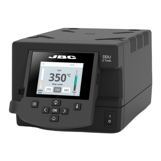
Page 5: Work Screen
w w w.jbctools.com Work Screen The DDE offers an intuitive user interface which provides quick access to station parameters. Original PIN: 0105 Status bar 17:14 Tool T245 in use ºC Temp. Levels Power indicator Power Port Displayed if temperature levels are activated Station Information... -
Page 6: Process Analysis
Process analysis By pressing Graphics in the main MENU, temperature and power figures in real time are displayed for each port. This helps you decide which tip to use to obtain the best quality solder joints. Graphics 17:14 Power (%) Temperature Power Temp... - Page 7 Soldering Net Remotely manage and monitor as many stations as your PC can handle. 1. Download the JBC Manager software and the user manual from www.jbctools.com/manager.html 2. Connect the stations via USB-B connector and the PC will automatically detect them.
- Page 8 Control Unit RS-232 connection Update the station software 1. Download the JBC Update File from 2. Insert the USB flash drive to the station. www.jbctools.com/software.html and save The icon is diplayed while updating. it on a USB flash drive. Preferably one with no other files.
-
Page 9: Maintenance
If necessary use a tool to lever it off. and replace it in the station. Fuse Fuse holder Fuse holder - Replace any defective or damaged pieces. Use original JBC spare parts only. - Repairs should only be performed by a JBC authorized technical service. - Page 10 Safety It is imperative to follow safety guidelines to prevent electric shock, injury, fire or explosion. - Do not use the units for any purpose other than soldering or rework. Incorrect use may cause fire. - The power cord must be plugged into approved bases. Be sure that it is properly grounded before use.
-
Page 11: Specifications
Specifications DDE-1B 120V 50/60Hz. Input fuse: 4A. Output: 23,5V. DDE-2B 230V 50/60Hz. Input fuse: 2A. Output: 23,5V. DDE-9B 100V 50/60Hz. Input fuse: 5A. Output: 23,5V. - Weight: 3,815 kg (8.41 lb) - Dimensions: 148 x 120 x 232 mm (5.8 x 4.7 x 9.1 in) - Page 12 Two-Tool Control Unit Power Cord Manual ....... 1 unit Unidad de control DDE..1 u. Cable de red ..... 1 unidad Ref. 0016160 Ref. DDE-1B (120V) Ref. 0010569 (230V) DDE-2B (230V) 0013671 (100/120V) DDE-9B (100V) w w w.jbctools.com Two-Tool Control Unit Ref.
- Page 13 w w w.jbctools.com Conexiones Trabaje simultáneamente con Unidad de control DDE 2 herramientas y enlace cada puerto con 1 módulo + 1 pedal (Peripherals). Conexión Soporte equipotencial Connector USB-B Periférico Toma de correinte Conector RJ12 para Robot Compatibilidades Seleccione los equipos que más se adapten a sus necesidades de soldadura Sistema de trabajo básico Periféricos / Módulos** Unidad de...
- Page 14 Funcionamiento El exclusivo sistema calefactor de JBC Nuestra tecnología revolucionaria es capaz de recuperar la temperatura de la punta de forma extremadamente rápida. Esto significa que el usuario puede trabajar a una temperatura más baja y mejorar la calidad de la soldadura. Esta temperatura se reduce aún más gracias a los modos de Sleep e Hibernation que incrementan hasta 5 veces la vida de las puntas.
- Page 15 w w w.jbctools.com Pantalla de trabajo La DDE-B presenta una interfaz de usuario intuitiva y ofrece un rápido acceso a los parámetros. PIN Original: 0105 Barra 17:14 de estado Herramienta T245 en uso ºC Temp. Levels Indicador de potencia Power Port Se muestra si los niveles de...
- Page 16 Análisis del proceso Pulsando sobre Graphics en el menú principal, se muestran las respuestas de temperatura y potencia en tiempo real de cada puerto. Esto le ayudará a decidir cuál es la punta más adecuada para obtener la mejor calidad en sus soldaduras. Graphics 17:14 Potencia (%)
- Page 17 Red de soldadura Remotely manage and monitor as many stations as your PC can handle. 1. Descargue el software JBC Manager y el manual de usuario de www.jbctools.com/manager.html 2. Conecte las estaciones a través del conector USB-B y el PC las detectará automáticamente.
- Page 18 Trabajar con Robots Gestione y monitorice la estación por medio de un sistema robotizado. Conecte la herramienta a la estación utilizando el convertidor CHB-A (Ref: CHB-A). Conecte su sistema robotizado al conector Robot de la estación (RJ12). Si lo necesita, el adaptador DB9-RJ12 está disponible (Ref: 0013772). Active la opción de robot en la estación y se mostrará...
-
Page 19: Mantenimiento
Si lo precisa, utilice una pequeña palanca. portafusibles en su sitio. Fusilble Portafusible Portafusible - Cambie cualquier pieza defectuosa o dañada. Utilice solamente recambios originales de JBC. - Cualquier reparación sólo se podrá realizar por un servicio técnico oficial JBC. - Page 20 Seguridad Es necesario cumplir estas normas de seguridad para prevenir cualquier choque eléctrico, heridas, fuego o explosiones. - No utilice el equipo para otros fines que no sea la soldadura o reparación. El uso incorrecto puede causar fuego. - El cable de red debe enchufarse en bases homologadas. Asegúrese de que está conectado a tierra correctamente antes de su uso.
-
Page 21: Especificaciones
Especificaciones DDE-1B 120V 50/60Hz. Fusible de entrada: 4A. Output: 23,5V. DDE-2B 230V 50/60Hz. Fusible de entrada: 2A. Output: 23,5V. DDE-9B 100V 50/60Hz. Fusible de entrada: 5A. Output: 23,5V. - Peso: 3,815 kg (8.41 lb) - Dimensiones: 148 x 120 x 232 mm (5.8 x 4.7 x 9.1 in) - Potencia máxima:... - Page 22 Two-Tool Control Unit Power Cord Handbuch ....1 Stück Two-Tool- Netzkabel ....1 Stück Ref. 0016160 Steuereinheit ....1 Stück Ref. 0010569 (230V) Ref. DDE-1B (120V) 0013671 (100/120V) DDE-2B (230V) DDE-9B (100V) w w w.jbctools.com Two-Tool Control Unit Ref. DDE-B Merkmale 2,8”...
- Page 23 w w w.jbctools.com Anschlüsse Arbeiten Sie gleichzeitig mit Steuereinheit bis zu 2 Werkzeugen und 1 Modul + 1 Fußschalter für jedes Werkzeug (Peripheriegeräte). Potenzialausgleichs- Ablage buchse USB-B Anschluss Peripheriegeräte Kabelbuchse RJ12-Anschluss für Robotersystem Kompatibilität Wählen Sie die Ausrüstung aus, die am besten zu Ihren Löt- und Entlötanforderungen passt, Funktionsfähiges einfaches System Peripheriegeräte** MSE-A /...
-
Page 24: Betrieb
Betrieb Das exklusive Heizsystem von JBC Unsere revolutionäre Technik ist dazu in der Lage, außerordentlich schnell die Spitzentemperatur zu erreichen. Dies bedeutet, dass der Benutzer bei geringerer Temperatur arbeiten und die Lötqualität verbessern kann. Die Spitzentemperatur wird zudem dank der Betriebsarten Sleep und Hibernation weiter gesenkt, wodurch die Spitzenstandzeit verfünffacht wird. - Page 25 w w w.jbctools.com Arbeitsbildschirm Die DDE-B bietet eine intuitive Benutzerschnittstelle, die schnellen Zugriff auf die Stationsparameter gewährt. Original PIN: 0105 Statusleiste 17:14 Angeschlos- T245 senes Werkzeug ºC Temp. Levels Leistungs- anzeige Power Port Angezeigt, wenn Temperaturstufen aktiviert sind Station Informationen Port ändern Menüoptionen Systemmeldungen (Statusleiste)
- Page 26 Prozessanalyse Beim Drücken von Graphics im Haupt-MENU, werden für jeden Port in Echtzeit Temperatur- und Leistungsangaben eingeblendet. Dies hilft Ihnen bei der Entscheidung, welche Spitze Sie für die beste Qualität der Lötverbindungen benutzen müssen. Graphics 17:14 Leistung Temperatur Power Temp Port 1 - T245 Siehe andere Portgrafik...
- Page 27 Lötnetz So viele Stationen, wie Ihr PC bewältigen kann, aus der Ferne steuern und überwachen. 1. Laden Sie die JBC Manager Software und das Benutzerhandbuch herunter unter www.jbctools.com/manager.html 2. Schließen Sie die Stationen per USB-B-Anschluss an und der PC wird sie automatisch erkennen.
- Page 28 Konverter Ref. CHB-A Steuergerät RS-232- Buchse Stationssoftware aktualisieren 1. Laden Sie den JBC Update File herunter 2. Stecken Sie den USB-Flashspeicher in die unter www.jbctools.com/software.html und Station. Das Symbol wird während des speichern Sie ihn auf einem USB-Flashspei- Aktualisierens angezeigt.
-
Page 29: Wartung
Halterung und setzen Sie sie erneut in die Falls notwendig, benutzen Sie ein Station ein. Werkzeug, um sie herauszudrücken. Sicherung Sicherungshalterung Sicherungshalterung - Jedes defekte oder schadhafte Teil austauschen. Nur Original-Ersatzteile von JBC verwenden. - Reparaturen dürfen nur von dem Vertragskundendienst von JBC durchgeführt werden. - Page 30 Sicherheit Die Sicherheits-Leitlinien müssen unbedingt eingehalten werden, um elektrischen Schlag, Verletzung, Feuer oder Explosion zu vermeiden. - Die Anlagen für keinen anderen Zweck verwenden als zum Löten oder Reparieren. Unsachgemäße Verwendung kann Feuer hervorrufen. - Das Netzkabel muss in zugelassene Steckdosen eingesteckt werden. Vergewissern Sie sich vor der Benutzung, dass sie korrekt geerdet ist.
-
Page 31: Spezifikationen
Spezifikationen DDE-1B 120V 50/60Hz. Eingangssicherung: 4A. Ausgang: 23,5V. DDE-2B 230V 50/60Hz. Eingangssicherung: 2A. Ausgang: 23,5V. DDE-9B 100V 50/60Hz. Eingangssicherung: 5A. Ausgang: 23,5V. - Gewicht: 3,815 kg (8.41 lb) - Abmessungen: 148 x 120 x 232 mm (5.8 x 4.7 x 9.1 in) - Page 32 装箱单 应包括以下项目: DDE 焊台 ....1 件 电源线 ......1 件 说明书 ......1 件 Ref. DDE-1B (120V) Ref. 0010569 (230V) Ref. 0016160 DDE-2B (230V) 0013671 (100/120V) DDE-9B (100V) w w w.jbctools.com Two-Tool Control Unit Ref. DDE-B 特点 2,8” 彩色 TFT 屏幕 USB-A 连接头 可倾斜显示器, 以便于阅读...
- Page 33 连接件 w w w.jbctools.com 可同时使用最多2个烙铁工 焊台 具, 每个工具可连接1个模 块和1个踏板 (外围模块) 等电压连接 支架 USB-B 连接头 外围模块 电源插座 机器人系统的 RJ12 连接头 兼容性 选择最适合您的焊接或脱焊需求的模块。 基本作业系统 外围模块** 烙铁头 MSE-A / 主机 支架 工具 MNE-A FSE-A P-005 系列 MVE-A T210-A C210 AD-SD T245-A C245 T470-A C245 T210-NA* C210 T245-NA* DN-SE...
- Page 34 操作 JBC 专有加热系统 在我们的革新技术的支持下, 焊嘴的温度可以极速恢复。 因此, 用户不仅可在较低的温度下进行作业, 还可改善其焊接质量。 此外, 睡眠和休眠系统可进一步降低焊嘴的温度, 从而使焊嘴寿命延长 5 倍。 1.作业 2.睡眠 3.休眠 长时间放置 在支架上 将工具从支架上提起时, 焊嘴 当工具放置在支架上时, 长时间没有使用后, 电源会切 将升温至选定的温度。 温度会下降到 断, 工具会冷却到室温。 预置睡眠温度。 17:14 17:14 17:14 T245 T245 T245 ºC Sleep Hibernatio n Actual Temp. 25ºC Tool in the stand Actual Temp.
- Page 35 工作屏幕 w w w.jbctools.com DDE 提供了直观的用户界面, 可通过此界面快速访问参数系统。 原始密码: 0105 状态栏 17:14 使用中的工具 T245 ºC Temp. Levels 电源指示器 Power Port 在温度位激活 的情况下显示 系统信息 变更端口 菜单选项 系统通知 (状态栏) 点击 INFO 可查看每个参数的描述。 USB 闪存盘已连接。 系统由电脑控制。 系统由机器人控制。 系统软件升级。 系统 工具 计数器 点击 INFO 启动此过程。 警告。 点击 INFO 可查看故障描述。 错误。 点击 INFO 可查看故障描述、 错误类 型以及处理方法。 外围模块...
- Page 36 过程分析 点击主 “菜单” 中的图形按钮, 可显示每个端口的实时温度和功率。 此信息有助于焊嘴 的选择, 从而得到最佳焊点。 图形 17:14 功率 (%) 温度 Power Temp Port 1 - T245 参见其他端口 图形 导出图形 将 USB 闪存盘插入 USB-A 连接器, 以 csv 格 式保存您的焊接过程。...
- Page 37 焊接网 w w w.jbctools.com Soldering Net 通过个人电脑远程管理和监测您的系统。 1.下载 JBC 管理软件及用户手册。 下载地址: www.jbctools.com/manager.html 2.通过 USB-B 连接器连接系统, 电脑将自动对其进行检测。 3.通知会显示在系统上。 功能 - 在电脑上设置所有系统参数。 - 同时组织多个系统并一起设置参数。 - 存储具体配置方案, 以便日后使用。 - 在电脑上分析这些系统的焊接图形, 并将其导出。 管理器软件 USB 集线器 任何 JBC 系统...
- Page 38 机器人作业 使用机器人系统管理和监测此系统。 1. 通过转换器将工具连接到系统端口。 2. 将机器人系统连接到该系统的机器人连接器上 (RJ12)。 必要时可使用 DB9-RJ12 适配器 (Ref:0013772) 。 3. 在系统设置中启用 “机器人” 选项, 将显示通知: 4. 请根据机器人通信协议设置您的 “机器人” 指令。 机器人通信协议查看网址: www.jbctools.com/jbcsoftware-menu-115.html 转换器 机器人 Ref. CHB-A 焊台 RS-232 连接 更新系统软件 1. 从www.jbctools.com/software.html 2. 将 USB 闪存盘插入系统。 网站下载 JBC 更新文件, 并保存在 USB 更新时将显示该图标。 闪存盘上。 首选不含其他文件的 USB 闪存盘。 JBC 更新文件...
- Page 39 维护 w w w.jbctools.com 在执行维护或存储操作前, 先让设备降温。 - 用玻璃清洁剂或湿布清洗屏幕。 定期清理 - 使用湿布清理外壳和工具。 酒精仅可用于清 理金属部件。 - 定期检查工具和支架的金属部分是否干净, 以 便该系统可检测工具状态。 - 储存前请清理并焊嘴表面并镀锡, 以免焊嘴氧 化。 生锈和脏污表面可降低焊点的热传递。 - 定期检查所有电缆和导管。 - 按如下方法更换熔断丝: 保险丝 保险丝支架 保险丝支架 1. 拉掉保险丝支架并拆除保险丝。 必要时使用 2. 将新保险丝装入支架并替换到系统中。 工具将其撬开。 - 更换任何受损或有缺陷的零件: 仅使用原装 JBC 零件。 - 维修工作仅由 JBC 授权的技术公司完成。...
- Page 40 安全 必须遵守安全指南, 以防止电击、 损伤、 火灾或爆炸事故的发生。 - 主机不得用于焊接或返工外的用途。 使用不当可能引起火灾。 - 电源线必须插入已通过审批的基座内。 使用前确保电源线正确接地。 拔下电源线时, 握住插头 (而不 是电线) 。 - 不得使用带电的部件。 - 不用时将工具放在支架上, 以激活睡眠模式。 焊 嘴、 工具和支架的金属部分可能在系统关闭时仍保持高温。 小心轻放 (包括在调整支架位置时) - 设备运行时必须有人时刻看管。 - 请勿覆盖通风口。 热量可能会引燃易燃品。 - 使用 “无残留” 的液体助焊剂, 避免与皮肤或眼睛接触造成过敏现象。 - 请小心留意焊接时产生的烟气。 - 保 持工作场所干净整洁。 工作时请佩戴防目镜和防护手套, 以免遭受伤害。 - 请务必小心可能烧伤皮肤的液态锡废物。 - 八 岁以上儿童, 体能、 感官或智力不全者以及经验不足者, 在合理监督下, 或在充分了解设备使用说 明及其潜在危险后,...
- Page 41 规范 w w w.jbctools.com DDE-1B 120V 50/60Hz.输入保险丝: 4A.输出: 23.5V DDE-2B 230V 50/60Hz.输入保险丝: 2A.输出: 23.5V DDE-9B 100V 50/60Hz.输入保险丝: 5A.输出: 23.5V - 重量: 3,815 kg (8.41 lb) - 尺寸: 148 x 120 x 232 mm (5.8 x 4.7 x 9.1 in) - 输出峰值功率: 每个工具 150W - 温度范围: 90 - 450 °C (190 - 840 ºF) - 闲时温度: 恒温 (静止空气) ±1.5 ºC (±3 ºF) - 焊嘴接地电阻: <2 ohms - 焊嘴接地电压: <2mV RMS - 环境温度: 10 - 40 ºC (50 - 104 ºF) - USB-A / USB-B /外围模块的连接器 - RJ12 连接器或机器人 符合 CE 标准 ESD 防护外壳 “驱肤效应”...
- Page 42 Exploded View · Despiece · Explosionszeichnung · 分解图...
- Page 43 有害物质含量表 w w w.jbctools.com 产品中有害物质的名称及含量 有害物质 部件名称 六价铬 多溴联苯 多溴二苯醚 铅(Pb) 汞(Hg) 镉(Cd) (Cr(VI)) (PBB) (PBDE) 烙铁头 手柄 电源线 主机 电源插座 保险丝 主开关 电位连接 变压器 线路板 O 表示该有害物质在该部件所有均质材料中的含量均在GB/T 26572 规定的限量要求以下。 X 表示该有害物质至少在该部件的某一均质材料中的含量超出GB/T 26572 规定的限量要求。...
- Page 44 Warranty JBC’s 2 year warranty covers this equipment against all manufacturing defects, including the replacement of defective parts and labour. Warranty does not cover product wear or misuse. In order for the warranty to be valid, equipment must be returned, postage paid, to the dealer where it was purchased.
Need help?
Do you have a question about the DDE-1B and is the answer not in the manual?
Questions and answers