Table of Contents
Advertisement
Quick Links
Advertisement
Table of Contents

Related Manuals for jbc DMU


Summary of Contents for jbc DMU
- Page 1 INSTRUCTION MANUAL 4-Tool Control Unit...
-
Page 2: Packing List
This manual corresponds to the following references: DME-9A (100V) DME-1A (120V) DME-2A (230V) Packing List The following items are included: Power Cord ....1 unit Manual ......1 unit 4-Tool Control Unit ....1 unit Ref. 0024077 (100V) Ref. 0028713 0023717 (120V) 0024080 (230V) Features... - Page 3 - color gris 200 mm Connections 130 mm 130 mm Work simultaneously with up to 4 tools and 1 module + 1 pedal for each tool (Peripherals). DMU Control Unit 100 mm Stands Equipotential connection 80 mm RJ45 connector for LAN...
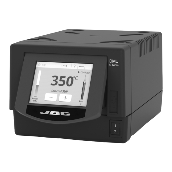
- Page 4 DMU Work Screen DMU offers an intuitive user interface which provides quick access to station parameters. Default PIN: 0105 Access Status Bar 17:14 to Menu MENU Options ºC Tool in use Power Selected 350º Indicator Power Port Port in use...
-
Page 5: Utilities Submenu
para manuales - color gris 200 mm Utilities Submenu 130 mm 130 mm It provides detailed graphics of tip temperature and power delivery in real time during solder joint formation for analysis purposes. This helps you decide how to adjust your process or which tip to use to obtain the best quality soldering. - Page 6 Temp. Levels Temp. Levels Power Port Power Power Port Port MSE Initial Set up* 1. After connecting the module, enter the 17:14 Peripherals Menu and select the port which you want to join with the module. Peripherals Port 2-DR 2. Select the module from the list of peripheral Pedal None Module...
-
Page 7: Operation
130 mm 130 mm The JBC Most Efficient Soldering System Our revolutionary technology is able to recover tip temperature extremely quickly. It means the user can work at a lower temperature and improve the quality of soldering. The tip temperature is further 100 mm reduced thanks to the Sleep and Hibernation modes which increase up to 5 times the life of the tip. - Page 8 Update the station software via USB connection: Cable USB AB Updater JBC Web Manager www.jbctools.com/manager.html Manage and monitor as many stations as your PC can handle by using JBC Web Manager. Data can be exported to another PC. any JBC station Cable USB AB...
-
Page 9: Maintenance
If necessary use a tool to lever it off. return it to the station. - Replace any defective or damaged pieces. Use original JBC spare parts only. - Repairs should only be performed by a JBC authorized technical service. - Page 10 Safety It is imperative to follow safety guidelines to prevent electric shock, injury, fire or explosion. - Do not use the units for any purpose other than soldering or rework. Incorrect use may cause fire. - The power cord must be plugged into approved bases. Be sure that it is properly grounded before use.
-
Page 11: Specifications
para manuales - color gris 200 mm Specifications 130 mm 130 mm 4-Tool Control Unit Ref. DME-9A 100V 50/60Hz. Input fuse: T-8A. Output: 23.5V 100 mm Ref. DME-1A 120V 50/60Hz. Input fuse: T-3.5A. Output: 23.5V Ref. DME-2A 230V 50/60Hz. Input fuse: T-3.15A. Output: 23.5V - Output Peak Power: 160W per tool - Temperature Range:... - Page 12 In order for the warranty to be valid, equipment must be returned, postage paid, to the dealer where it was purchased. Get 1 extra year JBC warranty by registering here: https://www.jbctools.com/productregistration/ within 30 days of purchase. This product should not be thrown in the garbage.
Need help?
Do you have a question about the DMU and is the answer not in the manual?
Questions and answers