Table of Contents
Advertisement
Quick Links
Advertisement
Table of Contents

Subscribe to Our Youtube Channel
Related Manuals for jbc DMU


Summary of Contents for jbc DMU
- Page 1 INSTRUCTION MANUAL 4-Tool Control Unit...
-
Page 2: Packing List
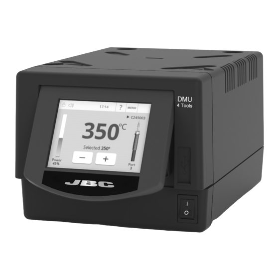
Ref. 0024077 (100V) Ref. 0028713 0023717 (120V) 0024080 (230V) Features DMU work simultaneously with up to 4 tools and 1 module + 1 pedal for each tool (peripheral modul for each tool needed). 2,8” Color TFT screen USB-A connector Tilt the display... -
Page 3: Connection Example
50 mm Desoldering Iron Ref. 0024227 Handle 40 mm Stand for DR560 Stand for Desoldering T210 & T245 Iron Handles Suction Filter Ref. 0821830 Module Cable Electric Desoldering Ref. 0024228 Module for DDU & DMU To another Peripheral Pedal P005... - Page 4 Compatibility Select the equipment that best suit your soldering or desoldering needs. Modular System Peripherals Control Cartridge Stand Tool MSE / MVE P405 Unit Range T210 C210 T245 C245 T470 T210N C210 T245N C245 AP250 C250 AM120 C120 PA120 AT420 C420 HT420 DS360...
- Page 5 - color gris 200 mm DMU Work Screen 130 mm 130 mm DMU offers an intuitive user interface which provides quick access to station parameters. Default PIN: 0105 100 mm Access 19:29 19:29 MENU Status Bar to Menu...
-
Page 6: Utilities Submenu
Utilities Submenu It provides detailed graphics of tip temperature and power delivery in real time during solder joint formation for analysis purposes. This helps you decide how to adjust your process or which tip to use to obtain the best quality soldering. Graphics Export graphics Insert a USB flash drive into the USB-A... - Page 7 para manuales - color gris 200 mm 19:29 19:29 MENU MENU 19:29 19:29 MENU MENU C245003 C245003 T245 T245 MSE / Pedal Initial Setup Sleep Sleep 130 mm 130 mm Tool in the stand Tool in the stand Selected 350ºC Selected 350ºC Actual Temp.
-
Page 8: Operation
Operation The JBC Most Efficient Soldering System Our revolutionary technology is able to recover tip temperature extremely quickly. It means the user can work at a lower temperature and improve the soldering quality. The tip temperature is further reduced thanks to the Sleep and Hibernation modes which increase up to 5 times the life of the tip. - Page 9 Lite. Note: Data can be exported to another PC. 40 mm any JBC station Cable USB A-B Manager Settings Change settings for a group of JBC stations at the same time. JBC Web Manager Register Settings Create graphs of the soldering process in real time showing power and temperature data.
-
Page 10: Maintenance
If necessary use a tool to lever it off. return it to the station. - Replace any defective or damaged pieces. Use original JBC spare parts only. - Repairs should only be performed by a JBC authorized technical service. - Page 11 para manuales - color gris 200 mm Safety 130 mm 130 mm It is imperative to follow safety guidelines to prevent electric shock, injury, fire or explosion. 100 mm - Do not use the units for any purpose other than soldering or rework. Incorrect use may cause fire. - The power cord must be plugged into approved bases.
- Page 12 Notes...
- Page 13 para manuales - color gris 200 mm Notes 130 mm 130 mm 100 mm 80 mm 60 mm 50 mm 40 mm...
- Page 14 Notes...
-
Page 15: Specifications
para manuales - color gris 200 mm Specifications 130 mm 130 mm 4-Tool Control Unit Ref. DME-9A 100V 50/60Hz. Input fuse: T-8A. Output: 23.5V 100 mm Ref. DME-1A 120V 50/60Hz. Input fuse: T-3.5A. Output: 23.5V Ref. DME-2A 230V 50/60Hz. Input fuse: T-3.15A. Output: 23.5V - Output Peak Power: 160W per tool - Temperature Range:... - Page 16 In order for the warranty to be valid, equipment must be returned, postage paid, to the dealer where it was purchased. Get 1 extra year JBC warranty by registering here: https://www.jbctools.com/productregistration/ within 30 days of purchase. This product should not be thrown in the garbage.
Need help?
Do you have a question about the DMU and is the answer not in the manual?
Questions and answers