Table of Contents
Advertisement
Quick Links
Advertisement
Table of Contents

Related Manuals for jbc DDU


Summary of Contents for jbc DDU
- Page 1 INSTRUCTION MANUAL 2-Tool Control Unit...
-
Page 2: Packing List
This manual corresponds to the following reference: - DDE-9C (100V) - DDE-1C (120 V) - DDE-2C (230 V) Packing List The following items are included: 2-Tool Power Cord ....1 unit Manual ....... 1 unit Control Unit ....1 unit Ref. - Page 3 - color gris 200 mm Connections 130 mm 130 mm Work simultaneously with DDU Control Unit up to 2 tools and 1 module + 1 pedal for each tool 100 mm (Peripherals). Equipotential Stand 80 mm connection USB-B...
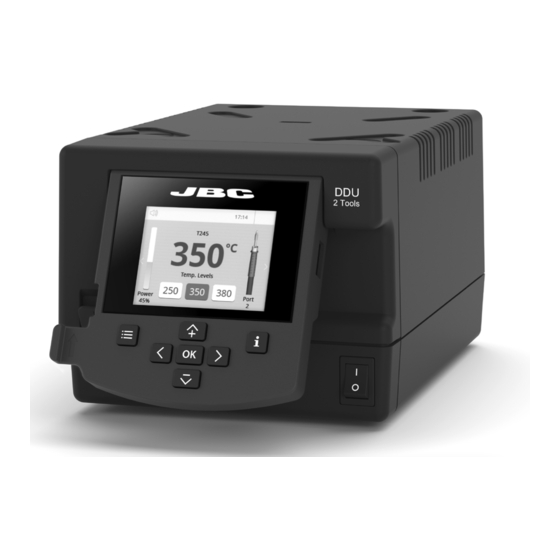
- Page 4 DDU Work Screen DDU offers an intuitive user interface which provides quick access to station parameters. Default PIN: 0105 Status Bar 17:14 17:14 Tool T245 T470 in use ºC ºC Power Temp. Levels Temp. Levels Indicator Power Power Port Port...
-
Page 5: Advanced Functionalities
Insert a USB flash drive into the USB-A connector to save your soldering process in csv format. Files Station update Download the JBC Update File from www.jbctools.com/software.html Insert the USB flash drive with the file downloaded to the station. Update System notifications The following icons will be displayed on the screen’s status bar. - Page 6 MSE Initial Set up* 1. After connecting the module, enter the 17:14 Peripherals Menu and select the port which you want to join with the module. Peripherals Port 2-DR 2. Select the module from the list of peripheral Pedal None Module connections.
-
Page 7: Operation
130 mm 130 mm The JBC Most Efficient Soldering System Our revolutionary technology is able to recover tip temperature extremely quickly. It means the user can work at a lower temperature and improve the quality of soldering. The tip temperature is further 100 mm reduced thanks to the Sleep and Hibernation modes which increase up to 5 times the life of the tip. - Page 8 Update the station software via USB connection: Cable USB AB Updater JBC Web Manager www.jbctools.com/manager.html Manage and monitor as many stations as your PC can handle by using JBC Web Manager. Data can be exported to another PC. any JBC station Cable USB AB...
-
Page 9: Maintenance
If necessary use a tool to lever it off. and replace it in the station. Fuse Fuse Holder Fuse holder - Replace any defective or damaged pieces. Use original JBC spare parts only. - Repairs should only be performed by a JBC authorized technical service. - Page 10 Safety It is imperative to follow safety guidelines to prevent electric shock, injury, fire or explosion. - Do not use the units for any purpose other than soldering or rework. Incorrect use may cause fire. - The power cord must be plugged into approved bases. Be sure that it is properly grounded before use.
-
Page 11: Specifications
para manuales - color gris 200 mm Specifications 130 mm 130 mm 2-Tool Control Unit Ref.: DDE-9C 100V 50/60Hz. Input fuse: T5A. Output: 23.5V 100 mm Ref.: DDE-1C 120V 50/60Hz. Input fuse: T4A. Output: 23.5V Ref.: DDE-2C 230V 50/60Hz. Input fuse: T2A. Output: 23.5V - Output Peak Power: 150W per tool - Temperature Range:... - Page 12 In order for the warranty to be valid, equipment must be returned, postage paid, to the dealer where it was purchased. Get 1 extra year JBC warranty by registering here: https://www.jbctools.com/productregistration/ within 30 days of purchase. This product should not be thrown in the garbage.
Need help?
Do you have a question about the DDU and is the answer not in the manual?
Questions and answers