
Subscribe to Our Youtube Channel
Related Manuals for AEMC instruments PEL 105


Summary of Contents for AEMC instruments PEL 105
- Page 1 Quick Start Guide ENGLISH Power & Energy Logger Model PEL 105 POWER & ENERGY LOGGERS WITH AEMC INSTRUMENTS ®...
- Page 2 Copyright Chauvin Arnoux , Inc. d.b.a. AEMC Instruments. All rights reserved. © ® ® No part of this documentation may be reproduced in any form or by any means (including electronic storage and retrieval or translation into any other language) without prior agreement and written consent from Chauvin Arnoux , Inc., as governed by United States and International copyright laws.
-
Page 3: Statement Of Compliance
Refer to our repair and calibration section at www.aemc.com/calibration. Serial #: Catalog #: 2137.57 / 2137.59 Model #: PEL 105 Please fill in the appropriate date as indicated: Date Received: Date Calibration Due: Chauvin Arnoux , Inc. - Page 4 PRODUCT PACKAGING (2137.57) (1) Large Classic Tool Bag Cat. #2133.73 (1) Power & Energy Logger Model PEL 105 Cat. #2137.57 (5) Black Test Leads and Alligator Clips (1) Power Adapter 110/240 V Cat. #2140.73* w/ Power Cord (*Replacement comes in Qty of 1) Cat.
- Page 5 PRODUCT PACKAGING (2137.59) (1) Large Classic Tool Bag Cat. #2133.73 (1) Power & Energy Logger Model PEL 105 Cat. #2137.59 (5) Black Test Leads and Alligator Clips (1) Power Adapter 110/240 V Cat. #2140.73* w/ Power Cord (*Replacement comes in Qty of 1) Cat.
-
Page 6: Symbols And Definitions
Example: hardwired equipment in fixed installation and circuit breakers. CAT II corresponds to measurements performed on circuits directly connected to the electrical distribution system. Example: measurements on household appliances and portable tools. Power & Energy Logger Model PEL 105 - Quick Start Guide... -
Page 7: Precautions Before Use
Any items with a degree of deteriorated insulation must be set aside to repair or discard. ■ All troubleshooting and calibration checks must be performed by competent, accredited personnel. Power & Energy Logger Model PEL 105 - Quick Start Guide... -
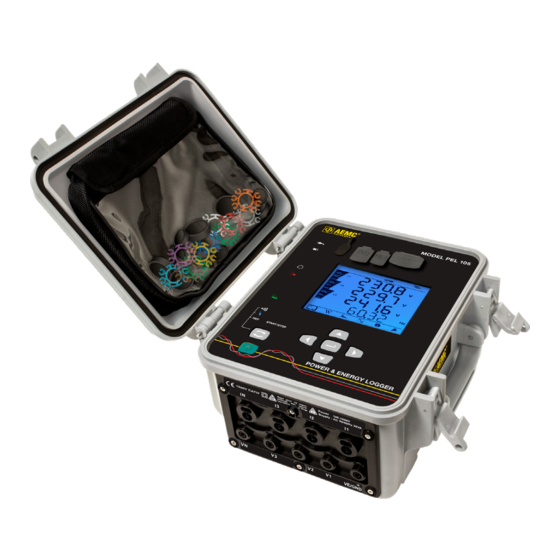
Page 8: Front Panel
AC power connected. OFF: Battery is fully charged. ■ Phase Sequence (Red) ON (blinks once per second): Phase rotation not as expected ■ OFF: Phase rotation order is as expected ■ Power & Energy Logger Model PEL 105 - Quick Start Guide... - Page 9 When not glowing, indicates the phase voltage feature is enabled ■ but the instrument is running on external AC or battery power. Blinks red when the phase voltage power feature is disabled. ■ Input Terminals SD Card Slot Power & Energy Logger Model PEL 105 - Quick Start Guide...
-
Page 10: Turning The Instrument On/Off
LEDs light up simultaneously. ■ Battery power: Press for two seconds and release it when all LEDs light up simultaneously. Power & Energy Logger Model PEL 105 - Quick Start Guide... -
Page 11: Installing Dataview
PEL Control Panel icon. Connecting to the Computer Before you can use the PEL Control Panel to communicate with your PEL 105, you must establish a connection between the instrument and the computer. There are six types of connections available: ■... - Page 12 “PEL 105” plus any additional characters you add via the PEL Control Panel. Click the name. 4. You are prompted to enter a pairing code, which for PEL 105 instruments is always 0000. After you enter the code, click Next.
-
Page 13: Wi-Fi Direct Connection
2. In the drop-down menu that appears, click the option Add an Instrument. 3. Select Ethernet (LAN or Wi-Fi) as the connection type, and complete the Add and Instrument dialog. If you need assistance, press the Help button. Power & Energy Logger Model PEL 105 - Quick Start Guide... -
Page 14: Installing The Sd Card
7. When the card is installed and ready for use, the LED glows steady green. To remove a card, press down on it until the card unclicks. It will pop up, allowing you to pull it from the slot. Power & Energy Logger Model PEL 105 - Quick Start Guide... - Page 15 Setting the Instrument Clock Before using the instrument, you should ensure the instrument clock is set to the correct time zone. By default the PEL 105 is set to Universal (UTC) time. To change this to another time zone, do the following: 1.
-
Page 16: Starting And Stopping A Recording
To view the recording session, connect the instrument to your computer running the PEL Control Panel, open the Help system, and follow the instructions for downloading and viewing recordings. Power & Energy Logger Model PEL 105 - Quick Start Guide... - Page 17 Distribution Systems and Hook-ups The following hookup diagrams and connection instructions are for distribution systems supported by the PEL 105. The instrument must be appropriately configured for the hookup type. Most configuration is performed through the PEL Control Panel, as described in the Help. Some configuration can also be done via the instrument’s front panel, as described in the user manual.
- Page 18 • V3 test lead to L3 • I1 probe to L1 • I1 probe to L1 • I2 probe to L2 • I3 probe to L3 • I3 probe to L3 Power & Energy Logger Model PEL 105 - Quick Start Guide...
- Page 19 • V3 test lead to L3 • IN probe to neutral • I1 probe to L1 • I1 probe to L1 • I2 probe to L2 • I3 probe to L3 Power & Energy Logger Model PEL 105 - Quick Start Guide...
- Page 20 • V2 test lead to conductor +2 • I1 probe to conductor +1 • IN probe to the common conductor • I1 probe to conductor +1 • I2 probe to conductor +2 Power & Energy Logger Model PEL 105 - Quick Start Guide...
- Page 21 • V3 test lead to conductor +3 • IN probe to the common conductor • I1 probe to conductor +1 • I2 probe to conductor +2 • I3 probe to conductor +3 Power & Energy Logger Model PEL 105 - Quick Start Guide...
-
Page 22: Repair And Calibration
Chauvin Arnoux , Inc. d.b.a. AEMC Instruments ® ® Phone: (800) 343-1391 (Ext. 351) Fax: (603) 742-2346 E-mail: techsupport@aemc.com www.aemc.com Power & Energy Logger Model PEL 105 - Quick Start Guide... -
Page 23: Limited Warranty
NOTE: You must obtain a CSA# before returning any instrument. Quick Start Guide Translations Visit our website to view and download a PDF version of this Quick Start Guide: Español Power & Energy Logger Model PEL 105 - Quick Start Guide... - Page 24 06/23 99-MAN 100428 v09 AEMC Instruments ® 15 Faraday Drive • Dover, NH 03820 USA Phone: (603) 749-6434 • (800) 343-1391 • Fax: (603) 742-2346 www.aemc.com © 2016 Chauvin Arnoux , Inc. d.b.a. AEMC Instruments. All Rights Reserved. ® ®...
Need help?
Do you have a question about the PEL 105 and is the answer not in the manual?
Questions and answers