Table of Contents
Advertisement
Quick Links
Advertisement
Table of Contents

Subscribe to Our Youtube Channel
Related Manuals for AEMC instruments 5070


Summary of Contents for AEMC instruments 5070
- Page 1 User Manual ENGLISH 5070 MEGOHMMETERS WITH AEMC INSTRUMENTS ®...
- Page 2 Copyright © Chauvin Arnoux , Inc. d.b.a. AEMC Instruments. All rights reserved. ® ® No part of this documentation may be reproduced in any form or by any means (including electronic storage and retrieval or translation into any other language) without prior agreement and written consent from Chauvin Arnoux , Inc., as governed by United States and International copyright laws.
- Page 3 For recalibration, please use our calibration services. Refer to our repair and calibration section at www.aemc.com. Serial #: Catalog #: 2130.30 Model #: 5070 Please fill in the appropriate date as indicated: Date Received: Date Calibration Due: Chauvin Arnoux , Inc. ®...
-
Page 4: Table Of Contents
TABLE OF CONTENTS 1. INTRODUCTION ................6 1.1 PRECAUTIONS FOR USE ............7 1.2 RECEIVING YOUR SHIPMENT ..........7 1.3 ORDERING INFORMATION ............. 8 1.3.1 Accessories and Replacement Parts ..........1.4 ACCESSORY INFORMATION ..........8 1.4.1 DataView Software ............... ® 2. - Page 5 3.9 CLEARING THE MEMORY ............. 44 3.10 CALCULATION OF ΔT FROM STORED DATA ....46 3.11 MAXIMUM OUTPUT VOLTAGE ..........47 3.12 LIST OF ERROR CODES ............47 4. MEASUREMENT FUNCTIONS ............48 4.1 AC/DC VOLTAGE ..............48 4.2 INSULATION MEASUREMENT ..........48 4.3 CAPACITANCE MEASUREMENT ..........
-
Page 6: Introduction
1. INTRODUCTION Thank you for purchasing a Megohmmeter Model 5070. For best results from your instrument and for your safety, read the enclosed operating instructions carefully and comply with the precautions for use. These products must be used only by qualified and trained users. -
Page 7: Precautions For Use
■ Match the contents with the ordering information. ■ Notify your distributor of any missing items. ■ If the equipment appears to be damaged, file a claim immediately with the carrier and notify your distributor at once. NOTE: Fully charge the instrument before use. Megohmmeter Model 5070... -
Page 8: Ordering Information
1.3 ORDERING INFORMATION Megohmmeter Model 5070............. Cat. #2130.30 Includes extra large tool bag, set of three 10 ft (5 kV) leads (red/black/blue with clips), one guard terminal jumper lead, USB cable type B, US 115 V power cord, rechargeable battery pack, and a USB stick with DataView software and user ®... -
Page 9: Product Features
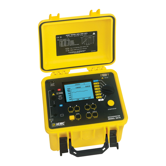
2. PRODUCT FEATURES 2.1 DESCRIPTION The Model 5070 megohmmeter is a top-of-the-line measuring instrument, portable, in a rugged housing with a graphic display. It is capable of operating from internal battery or line power. Main Functions: ■ Automatic detection and measurement of voltage/frequency/input current. -
Page 10: Control Features
V: 10 V steps from 40 to 1000 V and 100 V steps from 1000 to 5000 V) Insulation measurement with voltage step function (up to 5 steps Step Voltage can be configured). SET-UP User programming of the megohmmeter configuration. Megohmmeter Model 5070... - Page 11 Starts or stops the smoothing of displayed values during testing. SMOOTH TEMP Activates temperature correction Turns the display backlight ON or OFF Recalls saved data Printing measurement data is completed through DataView software. PRINT Browses through the screens accessible before, during, and after the GRAPH measurement Megohmmeter Model 5070...
-
Page 12: Display Features
Indicates the remaining battery charge. Indicates that the generated voltage is dangerous, V > 120 Vdc. Indicates that external voltage is present - this symbol is activated when the Start button is pressed if V > 25 Vrms. Megohmmeter Model 5070... -
Page 13: Special Functions
∆T for R/2 Calculate ∆T from Memory 5100V Maximum Output Voltage Set Default Parameter Clear Memory V Disturbance / V Output Buzzer Power Down 9600 / RS232 Baud Rate Europe Units 04.02.2004 Date (d.m.y) 15:47 Time (h:m) Megohmmeter Model 5070... -
Page 14: Instrument Configuration Parameters
You may now select the different voltage and adjust its value as just described. To exit the alarm setting function, press the DISPLAY button. This will bring you back to the top of the SET-UP menu. Megohmmeter Model 5070... - Page 15 SAMPLE TIME (m : s) Data from a timed run test can be stored in the Model 5070 at an interval you select. This storage interval can be as fast as once every 10 seconds to as slow as once every 10 minutes.
- Page 16 15 to 180 seconds for the second reading, both in 5 second increments. NOTE: The Model 5070 will not allow the time for the second reading to be set lower than the set time for the first reading.
- Page 17 *The minimum sample time is related to the total duration of the test (Total Run Time). It is equal to: Sample Time (seconds) = (h+1)*5 where h= total run time in hours. TEMPERATURE UNIT This function toggles the display between Fahrenheit and Celsius scales for temperature display. Range °C or °F Megohmmeter Model 5070...
- Page 18 For example, if you set the maximum voltage to 1250 V and place the rotary switch in the 5000 V position and start a test, the Model 5070 will only output 1250 V.
- Page 19 3%, 10%, or 20% BUZZER The Model 5070 is equipped with a buzzer that will emit an audible tone when a key is pressed, at regular intervals during a timed test, or continuously during an alarm trip. This function lets you toggle the buzzer on or off.
- Page 20 BAUD RATE This function lets you program in the communication speed between the Model 5070 and your computer. It must be set to 9600 for communication with DataView. Press the down arrow ▼ button until the blinking cursor is to the left of Baud Rate.
-
Page 21: Set-Up Menu
TIME (h:m) Time can be set here. A 24-hour clock is used in the Model 5070. Therefore 3:30pm would be programmed in as 15:30. Press the down arrow ▼ button until the blinking cursor is to the left of Time. To adjust the Time, press the right arrow ►... -
Page 22: Mode / Print Button
Timed Run + DD DAR (s/s) 30/60 This duration (Duration) and the time interval PI (m/m) 1/10 between samples (Sample) must be specified when the Timed Run mode is selected. Megohmmeter Model 5070... - Page 23 The samples and the curve are automatically stored with the final value of the resistance, if it is stored. During the measurement, if the position of the rotary switch is changed, or the START/STOP button is pressed, the measurement is stopped. Megohmmeter Model 5070...
- Page 24 DAR (s/s) SET-UP mode). 30/60 (m/m) 1.0/10 NOTE: In this mode, the DAR ratio will also be calculated automatically if the times needed to calculate it are less than the second time needed to calculate the PI ratio. Megohmmeter Model 5070...
- Page 25 In addition, changes in these ratios over time can be observed and used for preventative maintenance (e.g. to monitor the aging of the insulation of a population of rotating machines). Megohmmeter Model 5070...
-
Page 26: Secondary Function - Print
The screens vary depending on the mode selected before the measurement is started. This section, starting on the following page, shows typical screens that can be displayed for each test mode. Megohmmeter Model 5070... - Page 27 10 100 1 10 100 1 10 100 1 10 Information after pressing Information Displayed: DISPLAY: Measured resistance Measured resistance DC test voltage DC test voltage Residual current Residual current Measurement duration Measurement duration Insulation resistance bargraph DAR, PI, Capacitance Megohmmeter Model 5070...
- Page 28 AC/DC input voltage Frequency Input voltage 0.1V AC Leakage current Frequency 0.0Hz Date, time Input current 24.6pA Date: 09.28.2003 Time: 22:49 After 2nd Press on DISPLAY: 0.1 V 0.0Hz 24.6pA AC/DC input voltage Frequency Leakage current Voltage bargraph 1000 Megohmmeter Model 5070...
- Page 29 DD current Information after pressing Information Displayed: DISPLAY: Measured resistance Measured resistance DC test voltage DC test voltage Leakage current Leakage current Measurement duration Measurement duration DAR, PI, Capacitance Insulation resistance bargraph Residual current (calculation of DD) Megohmmeter Model 5070...
- Page 30 DD current 24. 6 pA 2.55 After 2nd Press on DISPLAY: After 1 Minute: Measured resistance DC test voltage AC/DC input voltage Leakage current Frequency Total test time Leakage current DAR, PI, Capacitance Voltage bargraph DD test current Megohmmeter Model 5070...
- Page 31 10 100 1 10 100 1 10 100 1 10 Information after pressing Information Displayed: DISPLAY: Measured resistance Measured resistance DC test voltage DC test voltage Leakage current Leakage current Remaining measurement time Remaining measurement time Insulation resistance bargraph DAR, PI, Capacitance Megohmmeter Model 5070...
- Page 32 Input voltage 0.1V AC Frequency Frequency 0.0 Hz Leakage current Input current 20.6pA Date, time Date: 10.18.2003 Time: 09:49 After 2nd Press on DISPLAY: 0.1 V 0.0Hz 20.6pA AC/DC input voltage Frequency Leakage current Voltage bargraph 1000 Megohmmeter Model 5070...
- Page 33 Information after pressing Information Displayed: DISPLAY: Measured resistance Measured resistance DC test voltage DC test voltage Leakage current Leakage current Remaining measurement time Remaining measurement time DAR, PI, Capacitance Insulation resistance bargraph Residual current (calculation of DD) Megohmmeter Model 5070...
- Page 34 DD current 11.5 5 pA 2.55 After 2nd Press on Display: After 1 Minute: Measured resistance DC test voltage AC/DC input voltage Leakage current Frequency Total test time Leakage current DAR, PI, Capacitance Voltage bargraph DD test current Megohmmeter Model 5070...
- Page 35 10 100 1 10 100 1 10 100 1 10 Information after pressing Information Displayed: DISPLAY: Measured resistance Measured resistance DC test voltage DC test voltage Leakage current Leakage current Remaining measurement time Remaining measurement time Insulation bargraph DAR, PI, Capacitance in process Megohmmeter Model 5070...
- Page 36 AC/DC input voltage Frequency Leakage current Voltage bargraph 1000 *NOTE: Because the test will stop after the DAR calculation, PI will not be calculated if the time values for this test are longer than those set for DAR. Megohmmeter Model 5070...
- Page 37 10 100 1 10 100 1 10 100 1 10 Information after pressing Information Displayed: DISPLAY: Measured resistance Measured resistance DC test voltage DC test voltage Leakage current Leakage current Remaining measurement time Remaining measurement time Insulation bargraph DAR, PI, Capacitance in process Megohmmeter Model 5070...
- Page 38 Input voltage 0.1V DC Frequency Frequency 0.0 Hz Leakage current Input current 20.6pA Date and time Date: 10.18.2003 Time: 10:03 After 2nd Press on DISPLAY: 0.1 V 0.0Hz 20.6pA AC/DC input voltage Frequency Leakage current Voltage bargraph 1000 Megohmmeter Model 5070...
-
Page 39: Secondary Function - Graph
■ If the result of your measurement is outside of the instrument’s range (the display shows the < or > symbol next to the reading), the Temperature Correction function cannot be applied. ■ Temperature correction is not available on Step Voltage tests. Megohmmeter Model 5070... - Page 40 ■ The Reference Temperature (Rc Reference Temperature) and the coefficient ΔT indicated and used for the calculation are those defined in SET-UP. Note: To store this calculation, press the 2nd + TEMP buttons again (OK is then displayed) before storing everything. Megohmmeter Model 5070...
-
Page 41: Smooth Button
Insulation Resistance Value is 991 MΩ. All the historical data is at 104°F. The corrected Insulation Resistance value corrected to 104°F for this motor is calculated by the Model 5070 to be 284.4 MΩ using the formula above when temperature correction is activated. -
Page 42: Alarm Button
Example: If the Obj is a 3-phase motor, then each test number will represent a specific insulation resistance measurement. e.g. - Test 1 = Phase A to housing Test 2 = Phase B to housing Test 3 = Phase C to housing and so on. Megohmmeter Model 5070... - Page 43 MEM mode without saving the results. Memory Capacity ■ Total memory space: 128 kB ■ Data management: 8 kB ■ Free memory space: 120 kB An insulation measurement requires 80 bytes. Therefore, approximately 1500 insulation measurements can be stored. Megohmmeter Model 5070...
-
Page 44: Second Function - Mr (Recall)
■ Select “Select Data Sets to Clear” by pressing the ► button. ■ Then, select each memory to be erased using the ▲ , ▼ buttons to choose it and the ► button to select it. The ◄ button will deselect it. Megohmmeter Model 5070... - Page 45 Clear memory: Select Data Sets to Clear Clear All All data sets will be cleared! O.K. CANCEL ■ The operation is confirmed or cancelled by pressing the ► button when the appropriate choice is highlighted as described above. Megohmmeter Model 5070...
-
Page 46: Calculation Of Δt From Stored Data
5078V 30°C Clear Memory 13 58 178.5MΩ 5078V 37°C V Disturbance / V Output 02 03 328.5MΩ 5078V 23°C Buzzer 02 02 328.5MΩ 5078V 23°C Power Down 02 01 328.5MΩ 5078V 23°C Baud Rate 9600 / RS232 Megohmmeter Model 5070... -
Page 47: Maximum Output Voltage
SET-UP mode to restore the default parameters (Set Default Parameter). Data Storage Error: When it is impossible to store data, the entire memory must be erased using the “Clear Memory” function in the SET-UP mode (see § 3.9). Megohmmeter Model 5070... -
Page 48: Measurement Functions
■ 500 V - 2 TΩ ■ 1000 V - 4 TΩ Input voltage 230V AC ■ 2500 V - 10 TΩ Frequency 50.0 Hz ■ 5000 V - 10 TΩ Input current 24.6nA Date: 09.28.2003 Time: 22:39 Megohmmeter Model 5070... - Page 49 ■ When the START button is pressed, if the external voltage of the terminals of the Model 5070 is greater that the value V peak defined in the set-up mode and described next, the insulation test is not started and an audible alarm is emitted;...
- Page 50 “+” and “-” terminals of 75 V will cause the Model 5070 to inhibit testing. (Vpeak = (0.03 x 2500 V) = 75 V) Similarly, if during the insulation test, an external voltage greater than the V peak...
-
Page 51: Capacitance Measurement
4.4 RESIDUAL CURRENT MEASUREMENT The residual current circulating in the installation is measured and displayed automatically upon connection to the installation, it is all measured during and after the insulation measurement. Megohmmeter Model 5070... -
Page 52: Operation
■ Press the START/STOP button again to stop the test. ■ The last result remains displayed until the next measurement is made or the switch is turned. ■ When the insulation measurement has stopped, the device under test will be automatically discharged by the Model 5070. Megohmmeter Model 5070... -
Page 53: Step Function Mode
Set-up mode for the profile selected. The screen on the right shows the default profile for Step Function Number 3. SET-UP Ramp 3 definition: Step Voltage Duration (h:m) 1000V 01:00 2000V 01:00 3000V 01:00 4000V 01:00 5000V 01:00 Total duration (h:m) 05:00 R(t) sample (m:s) 00:20 Megohmmeter Model 5070... - Page 54 ∆R 8.5MΩ final and initial test voltages. ∆V 4000V ∆R/(R*∆V) (ppm/V) ■ The slope of the curve in ppm/V. 0.28 320nF Capacitance ■ The capacitance. Pressing the GRAPH button displays the resistance versus applied test voltage curve. Megohmmeter Model 5070...
-
Page 55: Operation Examples
(e.g. dusty, damp cable or transformer insulation). In this case, alligator clips are preferable to hand-held test probes. As soon as the insulation measurement is stopped, the test circuit is automatically discharged using the instrument’s internal discharge feature. Megohmmeter Model 5070... - Page 56 Connection diagram for measurement of high resistance insulation a) Example of a motor (reduction of capacitive effects) BLUE BLACK BLUE JUMPER b) Example of a cable (reduction of superficial leak effects) Braid External insulator Insulator Cable BLUE Guard BLACK BLUE JUMPER Megohmmeter Model 5070...
-
Page 57: Dataview ® Software
USB drive, and double-click it to run the installation program. 3. The DataView setup screen appears. • In the upper left corner of the screen, choose the language version of the Setup interface. The Setup screens and dialogs will immediately appear in the selected language. Megohmmeter Model 5070... - Page 58 Control Panels take up disk space on the computer, so we recommend that you select Megohmmeter and deselect the rest unless you have other types of AEMC instruments. You should also check the option for the DataView Core, which is a requirement if you plan to create DataView reports.
-
Page 59: Megohmmeter Control Panel
For further information about using the Megohmmeter Control Panel, consult the Help system that comes with the product. You can access this Help by clicking the option Help at the top of the Control Panel's screen or by pressing F1 in the program. Megohmmeter Model 5070... -
Page 60: Specifications
NOTE: Vn = Test Voltage Nominal Current: >1 mAdc Short-circuit Current: <1.6 mA ± 5% Load Current: 3 mAdc approx when starting measurement NOTE: dlSt is the ratio of V Disturbance/V Output and is selectable in SET-UP mode. Megohmmeter Model 5070... - Page 61 ±5% of Reading + 3 cts ±15% of Reading + 10 cts DC Voltage Measurement (during insulation test): Range Resolution Accuracy 40.0 to 99.9 V 0.1 V 100 to 1500 V 1% of Reading ± 1 ct 1501 to 5100 V Megohmmeter Model 5070...
- Page 62 10 pA 100.0 to 999.9 nA 100 pA 1.000 to 9.999 µA 1 nA 5% of Reading 10.00 to 99.99 µA 10 nA 100.0 to 999.9 µA 100 nA 1000 to 3000 µA 1 µA 10% of Reading Megohmmeter Model 5070...
- Page 63 Typical changes in test voltages as a function of the load: 500 V Range 0.01 Resistance (MΩ) 1000 V Range 1200 1000 0.01 Resistance (MΩ) Megohmmeter Model 5070...
- Page 64 2500 V Range 3000 2500 2000 1500 1000 0.01 Resistance (MΩ) 5000 V Range 6000 5000 4000 3000 2000 1000 0.01 Resistance (MΩ) Megohmmeter Model 5070...
-
Page 65: Power Supply
Operating Range: 14° to 104°F (-10° to 40°C) during recharging of batteries 14° to 131°F (-10° to 55°C) during measurement 10 to 80% RH Storage: -40° to 158°F (-40° to 70°C); 10 to 90% RH Altitude: <2000 m Megohmmeter Model 5070... -
Page 66: Mechanical Specifications
0% to 20% Vn MΩ 0.1% R / % Vn 0.1% R / % Vn ± 5 cts test voltage *The terms DAR, PI, DD, and the capacity and current leak measurements are included in the quantity “MΩ.” Megohmmeter Model 5070... -
Page 67: Maintenance
■ Use a soft cloth lightly dampened with soapy water. Rinse with a damp cloth and then dry with a dry cloth. ■ Do not get water inside the case. This may lead to electrical shock or damage to the instrument. ■ Do not use alcohol, solvents, or hydrocarbons. Megohmmeter Model 5070... -
Page 68: Storage
Chauvin Arnoux , Inc. d.b.a. AEMC Instruments ® ® 15 Faraday Drive Dover, NH 03820 USA Phone: (800) 343-1391 (Ext. 351) Fax: (508) 698-2118 E-mail: techsupport@aemc.com www.aemc.com Megohmmeter Model 5070... -
Page 69: Limited Warranty
8.7 LIMITED WARRANTY The Megohmmeter Model 5070 is warrantied to the owner for a period of two years from the date of original purchase against defects in manufacture. This limited warranty is given by AEMC Instruments, not by the distributor from ®... -
Page 70: Appendix A. Utilizing The Guard Terminal
In the example of a cable, shown in the diagram below, connecting the guard terminal of the Model 5070 to the surface of the insulation will redirect surface leakage currents away from the true measured value of leakage current from the conductor through the insulation. - Page 71 Figure A-2 - No Guard Terminal Connected With the guard terminal connected, the surface leakage i1 is removed and has no effect on the reading. See Figure A-3. To Guard Terminal To EARTH To LINE Terminal Terminal Figure A-3 - Guard Terminal Connected Megohmmeter Model 5070...
-
Page 72: Appendix B. V Disturbance/V Output Feature
If the Model 5070 measures a voltage higher than the V Disturbance/V Output setting allows, no test voltage will be generated when the Start button is pressed. - Page 73 NOTES:...
- Page 74 NOTES:...
- Page 75 NOTES:...
- Page 76 05/22 99-MAN 100283 v30 AEMC Instruments ® 15 Faraday Drive • Dover, NH 03820 USA Phone: (603) 749-6434 • (800) 343-1391 • Fax: (603) 742-2346 www.aemc.com © Chauvin Arnoux, Inc. d.b.a. AEMC Instruments. All Rights Reserved.
Need help?
Do you have a question about the 5070 and is the answer not in the manual?
Questions and answers